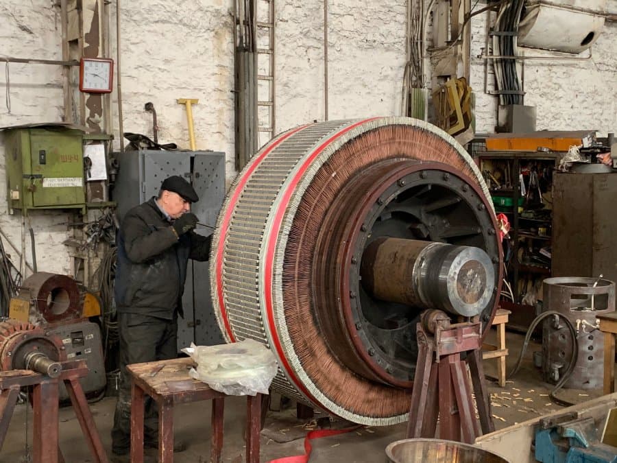
How is a commutator manufactured for a DC motor?
  1. // ELEKTROPROMREMONT
  2. Commutator manufacturing

How is a commutator manufactured for a DC motor?

Our article on commutator design, materials and faults already covers building a new one at overview level — eight steps, enough to grasp the principle. This article is its technical follow-on: a close look specifically at the process of manufacturing a new commutator from raw material, not at repairing an existing one. It answers the questions a production engineer or a shop foreman actually faces once repair is no longer an option and a commutator has to be built from a copper bar, a sheet of mica and a retaining or moulded construction.

Manufacturing a new commutator from scratch is not a rare exception — it is a routine job for any serious electrical repair shop. The reason is always one of four: the bars are worn past the remaining turning allowance, the commutator suffered severe damage from a flashover or overheating, no supplier anywhere stocks a replacement, or the machine is obsolete or long out of production, so no spare-parts market exists for it at all. In every one of these cases, the only way forward is the full production cycle — from copper bar stock to a finished, turned and tested commutator.

It is written for process engineers, production mechanics and repair-shop engineers who need to understand the actual sequence of manufacturing operations, what each step requires, and how it is checked — whether the job is done from the original manufacturer’s drawing or by reconstructing the geometry from a measured sample of a worn or damaged commutator.

When a commutator is manufactured from scratch instead of repaired

Repairing a commutator — turning, undercutting, replacing individual bars — is always cheaper and faster than building a new one, so a shop reaches for repair as long as it remains technically sound. Manufacturing a completely new commutator only becomes the right call in four situations.

01

The bars are worn past the remaining turning allowance

Every turning pass removes some copper, and the design documentation always specifies a wear limit — a minimum bar thickness below which the bar loses the mechanical strength it needs to resist centrifugal force and stay firmly seated in the retaining construction. If a commutator has already been through several repair turnings and the remaining bar thickness is approaching that limit, further turning is unsafe, and the only correct fix is a new set of bars — in practice, a new commutator.

02

Severe damage from a flashover or overheating

A flashover leaves melted patches on the working surface and leaves the inter-bar insulation charred and partly destroyed; prolonged local overheating from a failed riser joint or stray bearing currents can burn through the insulating sleeve between the stack and its hub. In these cases the damage usually spreads across a large share of the bars at once, a spot repair does not cover the full extent of it, and an attempt to turn the melted surface often shows the damage runs deeper than the allowable margin.

03

No supplier stocks a replacement

For a common production motor, a commutator can be ordered as a spare part. But for a one-off or purpose-built machine that has gone out of production — an old-type rolling-mill or traction motor, a generator the factory built in-house — no ready-made commutator exists on the market at all, and the lead time for a custom order anywhere would exceed the downtime the equipment can tolerate.

04

An obsolete or discontinued machine with no spare-parts market

A large share of the industrial fleet still in service consists of machines decades old, domestic or imported, whose manufacturer no longer exists or never supplied spare parts to this market in the first place. For equipment like this, manufacturing a new commutator in-house — from a drawing in the machine’s original nameplate documentation, or by reverse-engineering the existing part — is the only way to keep it running rather than scrapping a whole machine for the want of one assembly.

The manufacturing process, step by step

Building a commutator is a sequence of precision machining and press-assembly operations, where every later step depends on the quality of the one before it: an error made while stacking the bars cannot be corrected during turning, and a skipped cure bake will not show up until months into service, as bars working loose.

01

Preparing the copper stock and profiling the bars

The starting material is hard-drawn copper bar stock with a wedge-shaped (dovetail) cross-section, in a grade matched to the machine’s duty: grade M1 electrolytic copper for general industrial commutators, or copper alloyed with silver, cadmium or chromium for traction, rolling-mill and crane motors, where a higher softening temperature and resistance to work-hardening under the brush matter. The wedge cross-section — an asymmetric trapezoid — either arrives already rolled to profile, or is machined into a rectangular blank by milling or broaching. The bar is cut into individual blanks of the required length, with a small allowance left for facing the ends, and the number of blanks is set by the number of working sections in the armature winding (or a multiple of it, for some winding schemes).

02

Preparing the inter-bar insulation

Sheets of insulating material are die-cut or press-cut to the exact same profile as the bars and to the thickness the drawing calls for. The traditional material is micanite, pressed from flakes of natural mica bonded with shellac or epoxy; new commutators increasingly use reinforced synthetic mica tape or a glass-mica laminate for more consistent, predictable properties. The insulation’s thickness and hardness are chosen so it wears at roughly the rate of the chosen copper grade — that decision is made at this stage, because there is no fixing a poor match once the stack has been assembled.

03

Stacking the bars and insulation

Bars and insulation sheets are laid up in a circle around a temporary working sleeve or an expanding mandrel, alternating strictly one layer of copper with one layer of insulation until a complete cylindrical ring forms. During stacking, the builder checks that the risers land at an even pitch all the way around and that no bar sits skewed relative to the axis — any deviation left uncorrected here becomes run-out on the working surface after turning, and by then it cannot be fixed without taking the stack apart.

04

Pressing the stack

The assembled ring is clamped axially in a hydraulic press at a force read off a gauge and calculated for the specific diameter and bar count. Pressure is built up gradually, often in several stages with a short dwell between them — this lets the stack settle evenly, drives out trapped air between the layers, and seats every bar firmly against its neighboring insulation sheet. Too little pressure leaves the stack loose and prone to further settling in service; too much can deform or crack the brittle mica insulation.

05

Fitting the retaining construction

The pressed stack is locked into a permanent construction one of two ways. In a clamped V-ring (shrink-ring) construction, insulated conical rings are fitted onto both ends of the stack, their taper wedging the dovetailed bars inward toward the axis, with the tension held either by a retaining nut torqued to a specified value or by a heated steel band shrink-fitted onto the assembly — this construction stays serviceable, since it can be taken apart and re-clamped during a future repair. In a moulded (resin-cast) or through-bolt construction, the stack is cast in thermosetting resin under heat and pressure in a mould, forming a solid monolith with no metal retaining ring, or is clamped by insulated tie bolts through holes in the bars — a more compact solution common on medium-power production machines, but essentially not repairable if the stack fails internally.

06

Curing and stress-relief bake

Before the assembly reaches the lathe, it spends time in a thermostatically controlled oven, at a temperature and for a duration set by the insulation’s binder — this cures the shellac or advances the epoxy resin’s cure, and relieves the internal stresses the pressing step left behind. Cooling afterward is done slowly and under control, not in open air — uneven cooling introduces fresh internal stress rather than relieving the old stress. This step gets underrated, but it is what determines whether the commutator holds a stable geometry once the temporary tooling clamps come off for machining: a skipped or shortened bake does not show up immediately — it shows up months into service, as bars slowly working loose and run-out creeping up.

07

Rough turning

The stabilized drum is mounted in a lathe — on a mandrel, or in a chuck registered off the shaft bore — and the bulk of the metal is removed, taking out the eccentricity that inevitably built up during stacking and pressing. This pass deliberately leaves a machining allowance for the finish pass that follows — that allowance is what lets any remaining error be removed without risking undersize on the final diameter.

08

Finish turning to the final diameter

A finishing pass, with a fine feed and a sharp tool, brings the surface to the design diameter at the surface finish needed for good brush seating, and keeps the working surface concentric with the shaft bore within the drawing’s tolerance. This is the step where the resulting diameter and run-out are checked with a dial indicator, before moving on to machining the risers and the insulation.

09

Milling the riser slots

Once the outer surface is true, slots for the armature coil leads are cut or milled into the risers, with the cutter indexed to the bar pitch, and the burrs removed. How precisely this is done directly sets the reliability of the soldered or welded joint made later: a slot cut too narrow will not accept a coil lead without deforming the wire, one cut too wide leaves play that lets the joint work loose under vibration and eventually crack.

10

Undercutting the inter-bar mica

Right after turning, the mica between the bars sits flush with the copper — both materials just went through the same cutting pass. A thin slitting saw or a dedicated undercutting tool then removes mica down to the design depth below the copper all the way around, following the curve of the working surface so the groove depth stays even at every point. This keeps the insulation from standing proud in the first months of service, while the surface is still bedding in against the brushes, and builds in the margin needed for future repair turnings — each of which will require the mica to be undercut again.

11

Chamfering the bar edges after undercutting

Undercutting leaves a sharp copper edge along every bar, which chips under the brush within hours of running and scores the working surface of the neighboring bars if left untouched. A fine file or a dedicated tool bevels those edges to a small angle and a shallow depth, keeping a clean groove profile around the mica — the final operation that leaves the commutator ready to be mounted on the armature.

Quality control through the manufacturing process

Quality control on a new commutator is not one final check at the end — some parameters have to be verified while the stack is being assembled and pressed, because a defect found only after the commutator is mounted on the shaft often means taking the whole assembly apart again.

What is checkedHow it is checkedAcceptance criterion
Insulation resistance between neighboring barsMegohmmeter, all the way around, after pressing and again after finish turningReading meets the standard for the insulation class, with no sharp drop at any point
Bar-to-shaft (bar-to-hub) insulation resistanceMegohmmeter through the insulating sleeve, backed by a high-voltage withstand test where neededNo breakdown or reduced resistance that would point to sleeve damage during the press-fit
Concentricity and run-out of the working surfaceDial indicator against the shaft bore, while rotating the commutator slowlyRun-out within the drawing’s tolerance for that diameter and the machine’s operating speed
Final diameter and riser geometryCalipers and gauges, checked against the drawing or the measured sampleMatches the design diameter and coil-lead slot dimensions without manual fitting
How tightly each bar is seatedA light tapping test, plus checking the retaining nut or tie-bolt torque against specAn even, ringing sound all the way around, with no dull spot pointing to a loose bar

The insulation-resistance check is always repeated after finish turning and undercutting — machining can expose a hidden crack in the mica or a locally thinned spot in the insulation that was not visible before the extra layer of copper was removed.

Manufacturing from a drawing versus by reverse engineering

The manufacturing process itself is the same regardless of where the source data comes from, but how that data is obtained is what determines how difficult and risky the job will be.

Source of the dataWhat it guaranteesTypical situation
Original manufacturer’s drawing or machine nameplate documentationExact dimensions, material grades and tolerances from the manufacturer, with no measurement neededProduction machines and equipment with a full technical file on record at the plant
Reverse engineering from a worn or damaged commutatorDimensions are reconstructed by measuring the existing part and accounting for wear and prior repairsImported or obsolete equipment, one-off machines, or a plant with no documentation on file

Reverse engineering is standard practice, not a last resort, for imported machine tools and Soviet-era or pre-war equipment for which drawings never reached this plant, or were lost long ago. In that case, the segment count is worked out from the existing, even partially destroyed commutator — by direct count, or from the number of surviving armature coil sections; the pitch is found by dividing the working-surface circumference by the segment count, cross-checked against several independent measurements of neighboring bars; the diameter is taken from an undamaged patch of the working surface, or from the fit dimensions of adjacent parts if the surface itself has worn unevenly; and the riser geometry — including the slot’s angle and depth — is measured off the risers that are still intact.

Without documentation, the copper grade and the type of inter-bar insulation are inferred indirectly — from the metal’s hardness and colour, its behaviour under machining, and, when it matters, laboratory analysis of the composition. For machines with a known heavy duty cycle — traction, rolling-mill or crane drives — it is sound practice to specify an alloyed, higher-strength copper from the outset even if the original bars may have been plain electrolytic copper.

Why in-house manufacturing capability matters

For a common production motor, not having a commutator on the shelf is a matter of days or weeks waiting on a supplier. For a large, purpose-built or obsolete machine — a multi-tonne rolling-mill motor, an old-type traction motor, a one-off generator — no commutator being available on the open market means no ready-made part exists at all, and there is nothing to wait on.

This is exactly where an in-house production line — from cutting copper bar stock and die-cutting mica insulation through the press, the curing oven, the lathe and the milling equipment used for the risers and undercutting — stops being a convenience and becomes the only way to keep the equipment running. A shop able to build a commutator of any diameter and bar count, whether from a drawing or by reverse engineering, is not held hostage to a specific part sitting in some supplier’s warehouse, or to the schedule of a manufacturer that may no longer even exist.

Common mistakes in commutator manufacturing

  • choosing the inter-bar insulation’s thickness or hardness without matching it to the copper grade — a mismatched wear rate only shows up months into service;
  • pressing the stack in one sharp squeeze instead of building pressure up gradually with a dwell — this leaves hidden voids between layers;
  • skipping or shortening the cure bake to save time — the geometry starts to drift after the first thermal cycles in service;
  • jumping straight into finish turning after pressing, with no stress-relief bake and no rough pass left with a machining allowance;
  • milling the riser slots before finish turning the outer surface is complete — a later re-cut shifts the already-indexed slots out of alignment;
  • undercutting to a uniform depth "by eye" without accounting for slot width, bar count and the repair turnings still to come;
  • leaving sharp copper edges after undercutting without chamfering them;
  • reading off segment count, pitch or riser geometry from a single measured fragment of a worn commutator without cross-checking several independent points;
  • treating a moulded (resin-cast) construction as if it could be disassembled and spot-repaired the way a clamped construction can.

Frequently asked questions

How long does it take to manufacture a new commutator?

It depends on the diameter, the bar count, whether a drawing exists or reverse engineering is needed, and the construction chosen — a clamped construction typically takes more manual assembly work than a moulded one, but needs no mould to be made. As a rough guide, the full cycle — from copper bar stock to a finished, tested commutator — runs from a few days to a few weeks, and the cure bake is one of the steps that is not urgent but is not optional either, and should never be shortened just to save time.

Can a commutator be manufactured without a drawing?

Yes, by reverse engineering — the segment count, pitch, diameter and riser geometry are measured off the existing, even partially damaged commutator, and the material grades are inferred from hardness, metal colour and, where needed, laboratory analysis. This is standard practice for imported and obsolete equipment whose documentation never reached the plant or was lost long ago.

How does manufacturing differ from repairing an existing commutator?

Repair means turning, undercutting or replacing individual bars within a construction that is already partly worn but still has enough life left in it. Manufacturing is a full production cycle from raw material: new copper stock, new insulation, a new stack assembled and pressed, a new cure bake and complete machining. A shop moves to manufacturing exactly when the existing construction has run out of life, or is damaged badly enough that a spot repair can no longer bring it back.

Which construction should be chosen — clamped or moulded?

A clamped V-ring (shrink-ring) construction can be taken apart to replace individual bars or re-clamped during a future repair — which is why it is usually the choice for large, heavily loaded or one-off machines, where repairability matters. A moulded construction is more compact and common on medium-power production machines, but if the stack fails internally it is almost always replaced as a whole.

Why can the cure bake not be skipped?

Pressing only relieves part of the internal stress in the stack; the cure bake polymerizes or advances the insulation’s binder and relieves the rest. Skip that step and move straight to machining, and the geometry will look correct right off the production line — then start to drift within a few months of the thermal cycling a running machine puts it through, causing run-out and sparking.

Can a commutator be manufactured for a very old or imported machine that is out of production?

Yes — and this is exactly the kind of equipment in-house manufacturing is most often needed for, since no ready-made part exists on the open market at all. The source data comes from reverse engineering the existing, even damaged, commutator, and the manufacturing process itself is no different from building one off a drawing.

Does a new commutator need balancing after it is manufactured?

The commutator itself is checked for mass symmetry, or balanced as a standalone assembly, during manufacture, but the final balancing is always done together with the armature once the commutator is mounted on the shaft — it is the rotor’s total mass distribution, not the commutator alone, that determines the machine’s vibration level.

EPR (Elektropromremont) services

EPR (Elektropromremont) manufactures new commutators for DC motors and generators in-house, running the full production cycle — from the original manufacturer’s drawing, or by reverse engineering an existing worn or damaged part when no documentation survives.

The scope of work includes:

  • scoping the job: repairing the existing commutator or manufacturing a new one from scratch;
  • preparing copper bar stock and profiling the bars to a specific drawing or a measured sample;
  • cutting inter-bar insulation from micanite or a modern glass-mica material;
  • stacking, pressing and cure-baking the bar assembly;
  • fitting a clamped (V-ring) or moulded retaining construction under a specified clamping force;
  • rough and finish turning, milling the risers, undercutting and chamfering;
  • checking insulation resistance, concentricity and geometry at every stage of manufacture.

Important disclaimer

This material is for informational purposes. The values, diagnostic methods, scope of work and recommendations given here are general and do not replace the manufacturer’s technical documentation. The final decision for a specific machine is made from its own diagnostics and inspection, taking into account its type, power, design, duty, operating history and applicable standards.

Need a new commutator?

We manufacture a new commutator from a drawing or by reverse engineering an existing worn part — with full control of insulation, concentricity and riser geometry.

Get a consultation