Preparing the copper stock
Hard-drawn copper bar stock with a wedge-shaped (dovetail) profile is cut into individual bar blanks of the required length, matched to a drawing or to a measured sample from the commutator being replaced.
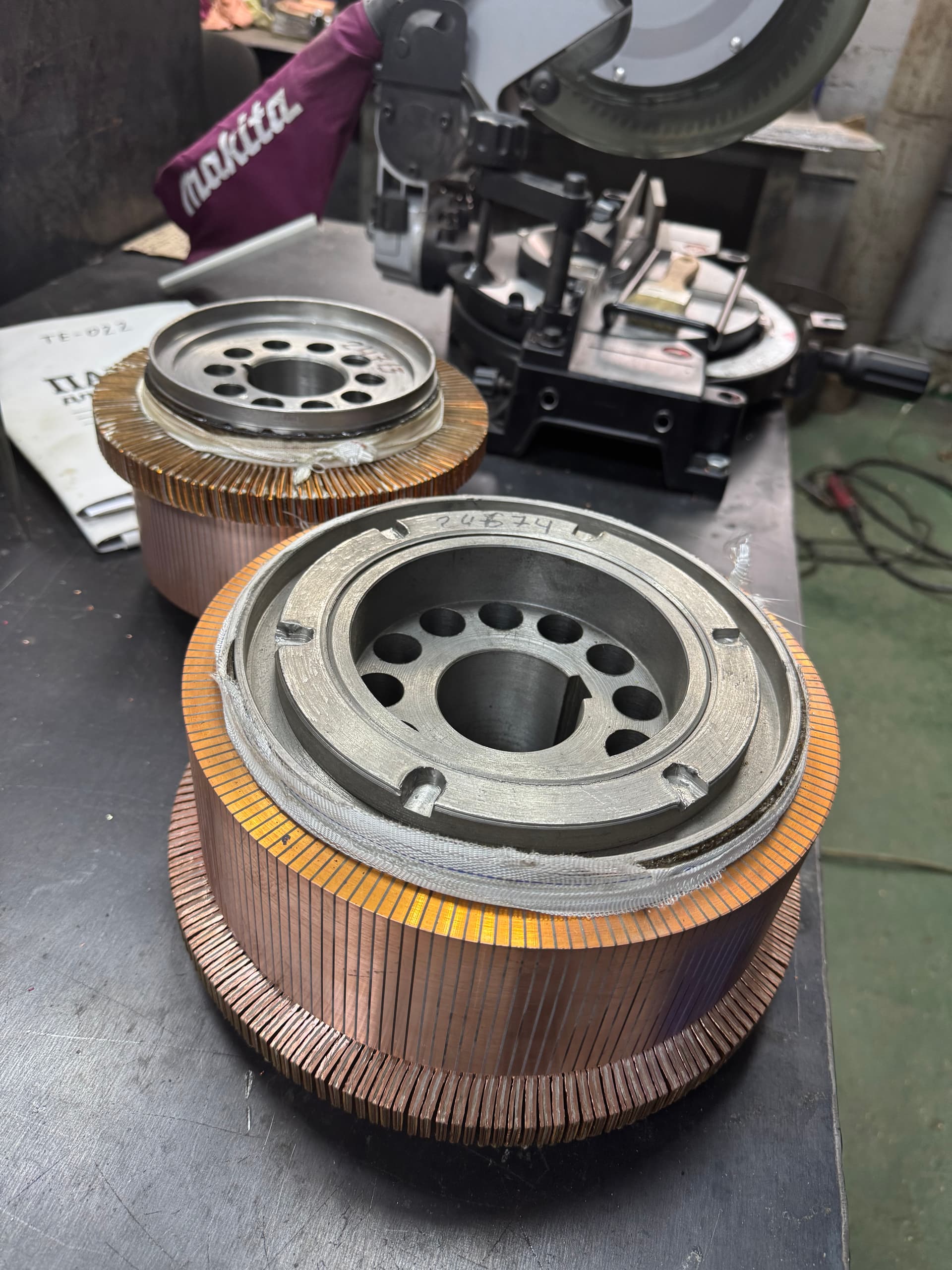
The commutator is one of the most critical assemblies in a DC machine: it converts the alternating electromotive force generated in the armature winding into direct current at a generator’s terminals, or, conversely, distributes the supply’s direct current across the winding sections of a running motor. Its design, materials and surface condition directly determine the quality of the brush-commutator contact, the level of sparking, and the service life of the whole machine.
This article merges two questions that are inseparable in practice: what a commutator is, what it is built from, and why it fails, together with how a new one is manufactured and how it is reconditioned during repair. Understanding the design is impossible without understanding the manufacturing process, and a proper repair rests on the same principles a commutator is built to at the factory.
It is written for technicians who service DC machines — electricians, repair mechanics and engineers who need to understand a commutator’s construction, select materials for replacing bars or insulation, or judge the scope of repair after a defect is found.
A commutator is a cylindrical assembly on the armature shaft, built from individual copper bars (lamellae) insulated from one another. Each bar is connected to a particular section of the armature winding, and stationary brushes, spring-loaded against the commutator surface, provide the sliding electrical contact between the rotating armature and the machine’s external circuit.
As the armature turns through the field of the poles, an electromotive force is induced in each winding section that alternates direction — a conductor passes under a north pole, then a south pole, in turn. If that section could be connected to the external circuit directly, its terminals would carry an alternating voltage. The commutator, together with the brushes, acts as a mechanical rectifier: the moment a brush moves from one bar to the next, it switches the connection so the machine’s terminals always see a voltage of one polarity, even though the current in any single section stays alternating.
In a DC generator, this process turns the armature winding’s alternating EMF into direct current for the load. In a DC motor, the commutator works in reverse: it distributes the direct current arriving through the brushes across the winding sections, switching between them in turn — which keeps the current in the armature conductors alternating in step with the pole positions, exactly what is needed to produce a steady, one-directional torque.
The moment a brush switches a section over is called commutation, covered in depth in the article on brush sparking. What matters for the commutator itself is that its design, geometry and surface condition are what determine how smoothly that commutation happens.
A commutator is built from lamellae — copper bars with a wedge-shaped (dovetail) cross-section, a shape that lets them be assembled into a solid cylinder: each bar’s side face locks the next one against radial movement. The number of bars matches the number of working sections in the armature winding (or a multiple of it, for some winding schemes).
A thin sheet of inter-bar insulation, cut to the same profile, sits between neighboring bars — traditionally micanite, pressed from flakes of natural mica bonded with a shellac or epoxy binder; new and repaired commutators increasingly use reinforced synthetic mica tape or a glass-mica material. The insulation’s thickness and material are chosen so it wears at roughly the same rate as the copper, which is essential for keeping the working surface’s geometry stable over the commutator’s whole service life.
One end of each bar carries a raised lug called a riser (also called a tang), with a slot into which the leads of two adjacent armature coils are laid and joined. That joint is made by soldering with tin-lead or silver solder, or by resistance or TIG welding. The bar’s opposite, cylindrical face forms the working surface the brushes ride on — its geometry, surface finish and the condition of the inter-bar insulation are what determine the quality of the brush-commutator contact.
Centrifugal force acts on every bar as the commutator spins, trying to pull it away from the axis, so the individual copper bars have to be clamped into a rigid monolith and fixed relative to the shaft. Industrial commutators use three main constructions.
| Construction | How the bars are clamped | Repairability |
|---|---|---|
| Clamped V-ring (shrink-ring) construction | Two insulated V-shaped rings clamp the dovetail ends of the bars from both sides; a retaining nut or a shrink-fitted band holds the tension | Can be disassembled to replace individual bars or insulation and then re-clamped to the same stack pressure |
| Through-bolt construction | Insulated tie bolts pass through holes in the bars and clamp the stack between two end rings | Convenient to take apart for repair, common on medium-sized commutators |
| Moulded (resin-cast) construction | Bars and mica are pressed and cast in thermosetting resin into a solid monolith, with no metal retaining ring | Essentially not repairable; a failed stack is usually replaced as a whole unit |
The construction chosen depends on the machine’s size, its duty and how many units are being produced. Clamped and through-bolt constructions dominate in industrial repair, since they allow a commutator to be taken apart, a bar or insulation piece replaced, and the assembly re-clamped to the same stack pressure.
A commutator is press-fitted onto the armature shaft directly, or, more often, onto a separate hub that is itself pressed onto the shaft with an interference fit and secured with a key or a taper. Because neighboring bars sit at different electrical potentials while the shaft must stay at earth potential, the whole conductive commutator stack is insulated from the hub and shaft by a cylindrical or conical sleeve — historically pressed micanite, and today more often a glass-epoxy laminate or another layered dielectric chosen for high mechanical and thermal strength.
This insulation is checked separately from the inter-bar insulation, because a breakdown here can come not only from gradual material ageing but also from mechanical damage during the press-fit, or from moisture or carbon dust tracking along the sleeve surface. That is why a commutator insulation-resistance test always includes a bar-to-shaft check, not only bar-to-bar readings.
Commutator materials are chosen not just for electrical conductivity but also for mechanical strength, hardness and resistance to heating during sparking or a brief overload.
| Material | Where it is used | Main advantage |
|---|---|---|
| Grade M1 electrolytic, hard-drawn copper | Standard commutators for general industrial machines | High conductivity, familiar machining practice |
| Silver-bearing copper (Cu-Ag alloy) | Traction, rolling-mill, crane and other heavily loaded motors | Higher softening temperature, resists work-hardening under the brush |
| Cadmium or chromium copper (Cu-Cd, Cu-Cr) | Commutators under elevated mechanical and thermal stress | Increased hardness and wear resistance while keeping conductivity |
| Natural mica (muscovite, phlogopite) in micanite | Inter-bar insulation | High dielectric strength, wear rate matched to copper |
| Glass-mica tape | Inter-bar insulation on new and repaired commutators | More consistent properties, less dependent on the impregnating varnish |
| Glass-epoxy laminate, pressed micanite | Insulation between the commutator and its hub or shaft | High dielectric and mechanical strength under heat |
Heavily loaded commutators — on traction, rolling-mill and crane motors — use copper alloyed to raise its softening temperature and resistance to work-hardening under the brush; general industrial commutators do fine with electrolytic hard-drawn copper. Inter-bar insulation must always be matched so its wear rate tracks the copper’s — mica that is too hard is left proud, mica that is too soft washes out early.
Building a new commutator is a multi-stage process of precision machining and press assembly, in which every step affects how the finished assembly performs.
Hard-drawn copper bar stock with a wedge-shaped (dovetail) profile is cut into individual bar blanks of the required length, matched to a drawing or to a measured sample from the commutator being replaced.
The bars are arranged in a circle around a temporary or working mandrel, alternating with pre-cut sheets of inter-bar insulation of the same profile, until a full ring forms with the risers aligned.
The assembled stack is clamped axially in a hydraulic press at a controlled force and, if the insulation uses a shellac binder, heated to cure it — this removes voids and seats the bars evenly against each other.
Insulated conical rings are fitted at both ends of the stack and secured either by shrink-fitting a heated retaining band onto the assembly or by tightening a retaining nut or tie bolts to a specified torque, producing a rigid pressed drum.
The assembled drum is mounted in a lathe and turned first roughly, then to a fine finish at the design diameter, keeping the working surface concentric with the shaft bore.
Slots for the armature coil leads are cut or milled into the risers and deburred — how well this is done directly affects the reliability of the soldered or welded joint made later.
The mica between bars is recessed below the copper to the design depth already at the manufacturing stage, which prevents the insulation from standing proud in the first months of service, while the working surface is still bedding in.
A megohmmeter checks the insulation resistance between neighboring bars and between the bars and the shaft, a dial indicator checks run-out and ovality of the working surface, a light tapping test checks how tightly each bar is seated, and the retaining nut’s torque is checked against the specification.
Most commutators outlast several sets of brushes, and often an armature rewind too, given regular maintenance. The main repair operations are carried out in the following order.
The working surface, risers and inter-bar insulation are examined for burning, grooves, high bars and cracked joints, to decide how far the repair needs to go.
A light finishing cut, either on a lathe or in the machine, removes burning, grooves and ovality while taking off as little copper as possible, to preserve the bars’ remaining thickness for future repairs.
The mica is recessed below the copper again, using a saw blade matched to the mica’s width or a dedicated undercutting tool, to a uniform depth all the way around — every turning pass inevitably leaves the mica proud again and calls for a fresh undercut.
The sharp edges left by undercutting are chamfered with a fine file or a dedicated tool — left as they are, they chip under the brush and score the working surface.
On clamped or through-bolt commutators that can be disassembled, individual burnt or cracked bars and the insulation next to them are replaced with new parts cut to the same profile, then the stack is pressed back together and the clamping force restored. On moulded commutators, this kind of spot repair is generally not possible.
Every riser-to-coil joint is inspected for cracks, oxidation or a cold solder joint and, where needed, resoldered or rewelded — this is the defect most often behind sparking that repeats at the same spot on the commutator every revolution.
Removing copper during turning, or replacing individual bars, shifts the mass distribution, so after a substantial repair the commutator and armature are checked and, if needed, rebalanced.
Before the machine goes back into service, the same checks used on a new commutator are repeated: insulation resistance between bars and to the shaft, run-out of the working surface, and, where possible, a surge test of the armature winding through the bars.
Most commutator defects are linked to one another — one lapse in maintenance sooner or later shows up as another. The table below covers the most common faults in the commutator itself, separate from brush and brush-holder defects, which are covered in their own article.
| Fault | Likely cause | What to check or do |
|---|---|---|
| Heavy sparking and flashover | Covered in depth in the article on brush sparking | Check the brush-commutator contact, commutation and load |
| High mica (insufficient undercutting) | Insulation not recessed below copper after turning | Measure slot depth, undercut again if needed |
| Chipped bar edges | Excessive undercutting or no chamfer applied | Inspect the bar edges, chamfer if needed |
| Loose bars, rattling | Lost clamping force, a loosened nut or band, thermal cycling | Check run-out, tap-test the bars, retighten the clamp |
| Burnt or pitted bars | Prior heavy sparking, a flashover, or stray bearing currents | Inspect the surface, measure insulation resistance, assess whether bars need replacing |
| A failed riser joint | A crack or cold solder joint, vibration, local overheating | Measure resistance between neighboring bars, check the solder or weld |
| Run-out or ovality of the working surface | Incorrect turning, a bent shaft, a loosened stack, worn bearings | Measure run-out with a dial indicator, check the shaft and bearings |
A slip ring is a solid ring that only carries current to the rotor winding — it switches nothing. A commutator is built from bars insulated from one another and performs mechanical commutation, switching between armature winding sections in step with rotation.
The wedge (dovetail) profile lets the bars form a self-locking cylinder — each bar holds its neighbor against radial movement without needing a separate fastener for every segment.
It is recessing the inter-bar mica below the level of the copper. Because copper and mica wear at different rates, and every turning pass removes some of both, undercutting has to be repeated after every substantial turning of the commutator.
Surface work — turning, undercutting, chamfering — is done the same way as on any other construction. But replacing a single bar or restoring the stack’s clamping force is usually not possible, so an internal failure on this type more often means replacing the whole commutator.
Yes. Copper alloyed with silver, cadmium or chromium has a higher softening temperature and resists work-hardening and surface melting under the brush better during brief heavy sparking, although correct brush selection and proper commutation remain the main factor.
As part of scheduled maintenance of the brush-commutator assembly, and always after sparking, vibration or elevated commutator temperature appears, or after replacing brushes or repairing the armature.
Much of the assessment — visual inspection, bar-to-bar resistance, thermal imaging under load, and often run-out — can be done through inspection covers or by lifting the brushes, without a full teardown.
EPR (Elektropromremont) manufactures and repairs commutators for DC motors and generators in-house — from turning individual bars to building a complete new commutator from a drawing or from a measured sample of the removed part.
The scope of work includes:
This material is for informational purposes. The values, diagnostic methods, scope of work and recommendations given here are general and do not replace the manufacturer’s technical documentation. The final decision for a specific machine is made from its own diagnostics and inspection, taking into account its type, power, design, duty, operating history and applicable standards.
We inspect the commutator, carry out turning, undercutting or a full manufacture of a new one, and check insulation and geometry throughout.