What’s the difference between a coil, a section and a coil group?
Coil and section are usually synonyms — an individual winding element with a set turn count. A coil group is several coils of one phase and pole group connected together.
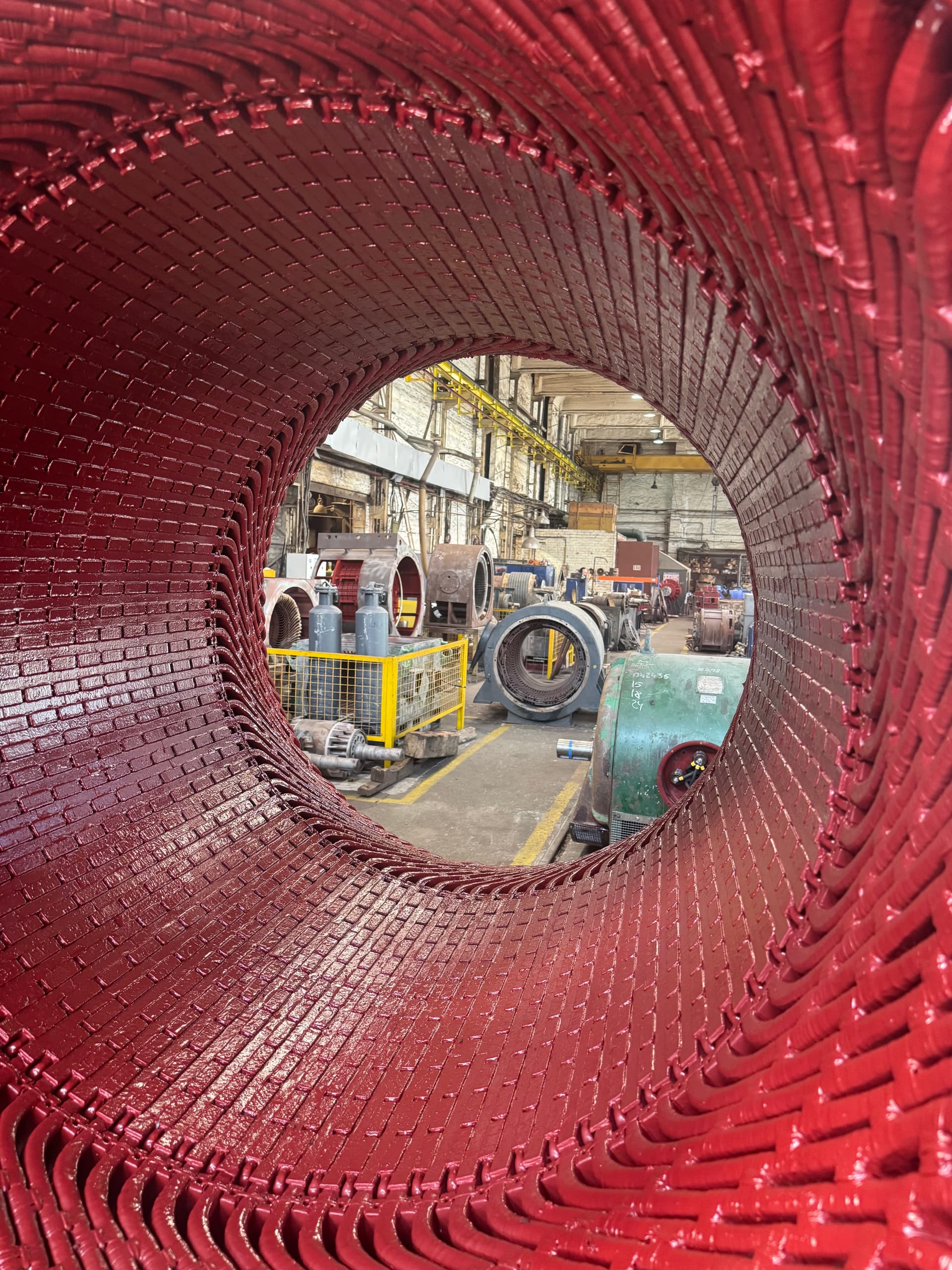
Manufacturing stator coils is the process of forming electrically and mechanically finished elements of a future stator winding out of magnet wire or copper bar. The quality of a single coil directly affects the whole machine — an error in one coil can cause phase asymmetry, excess current, an interturn short, or the motor failing again after repair.
A coil (or section) is an individual winding element with a set number of turns, a shape, a pitch, insulation, and leads. A coil group is several coils of one phase and pole group connected together. The stator winding is the complete system of every coil, every connection, the phase leads, and the insulation elements fitted into the core. One correctly made coil therefore does not by itself guarantee the whole stator will work correctly.
Making stator coils is not simply winding wire onto a form — it is a complete process: recovering the winding data, choosing the conductor, designing the form, winding under controlled tension, applying insulation, pressing, impregnation, electrical testing, and geometric inspection.
Soft random-wound coils are made mostly from round enameled wire — typical of low-voltage motors of small and medium power with semi-closed slots. The advantage is simple technology and flexibility during insertion; the drawback is harder control over the inner turns and heavy dependence of the result on impregnation quality.
Hard formed coils are made from rectangular wire or insulated copper bar and are used in high-voltage motors, large generators, and synchronous machines. Such a coil has its final geometry and ground-wall insulation already set before it goes into the stator, so form and individual-test requirements are much stricter. Large generators and specialized machines may use bar-type elements with transposed conductors and internal cooling — a separate, highly specialized operation.
A coil cannot be made just from the approximate shape of an old one — the number of slots, poles and phases, the winding type, the pitch, the turn count and parallel conductors, wire size, connection scheme, and insulation type all need to be established. Sources of this data include the factory drawing, repair documentation, an undamaged old coil, or an electromagnetic calculation — the most reliable approach compares several independent sources.
The old winding may already have been repaired, and the turn count, pitch, wire cross-section, or connection scheme may have been changed in the process — so blindly copying an old coil risks repeating the earlier mistake.
A winding can be single- or double-layer, concentric, lap, or wave, with full or fractional pitch. Pitch — the distance between a coil’s two slot sides, expressed as a number of slot spans (e.g. 1–10) — affects the induced EMF, the field’s harmonic content, end-winding length, and noise. Fractional pitch is used to suppress specific harmonics and save copper, but pitch must never be changed just to make insertion easier.
Turn count affects the magnetomotive force, the working magnetic flux, no-load current, starting torque, and heating — even a small error can change the machine’s characteristics. It is established by direct count during teardown, checking wire length, an electromagnetic calculation, and comparison with a similar machine, ideally checking several old coils from different phases.
A turn is a closed conductor loop that links the magnetic flux; if a turn is made of several parallel conductors, it is still one turn, just with a larger total copper cross-section.
Round wire is used mostly in low-voltage motors and random-wound coils for its flexibility and easy winding. Rectangular wire is used in large and high-voltage machines for better slot fill and more stable geometry in formed coils — but it bends less easily and demands tighter control of bend radius and transposition.
A wire’s measured outer dimension includes the copper, the enamel, and any contamination, so cross-section should never be judged with calipers alone — a control sample needs to be stripped, or the cross-section calculated from resistance and length. Increasing cross-section without a calculation can complicate insertion, hurt varnish penetration, and rule out fitting the slot wedges — thicker wire is not always better.
For a soft low-voltage coil, the main turn insulation is the wire’s enamel, supplemented with glass tape or insulating sleeving; ground-wall insulation is largely provided by the slot liner and the impregnating material. A formed high-voltage coil has reinforced turn and ground-wall insulation, a semi-conductive slot coating to even out the electric field, and a graded corona-protection coating at the slot exit — it is almost a finished insulated product before it ever goes into the core.
Using one high-temperature-class material does not automatically raise the class of the whole winding — the weak link can remain the wire’s enamel, a tape, a varnish, or a phase separator. For motors run from a variable frequency drive, elevated interturn voltage from steep pulse fronts needs to be accounted for — an inverter-duty wire, reinforced turn insulation on the first turns of a phase, or an output filter may be needed.
Dimensions for the form are taken from an undamaged coil, the stator before teardown, or a drawing — an overheated failed coil is not a reliable reference, since it may have deformed or expanded. The form must give the right pitch, consistent length across every coil, and easy removal without damaging the enamel.
Before winding a production batch, one control coil is made and checked for pitch, turn count, dimensions, mass, and resistance, and where possible test-fitted into the stator before the whole batch is produced.
Before winding, the wire’s grade and condition are checked; coils for one phase should ideally come from a single confirmed batch of material. The turn counter must be verified and backed up by process control — a coil with the correct turn count but wrongly positioned leads can be unusable for mounting.
Wire tension must give a tight, stable shape without stretching the copper or damaging the enamel. Too little tension produces a loose coil and unstable geometry; too much damages the enamel, reduces the cross-section, and cracks rectangular wire at the bends. When a turn is made of several parallel conductors, equal length and correct transposition are essential — transposition should never be altered on one’s own initiative, since it equalizes induced voltages and reduces circulating currents.
After winding, the coil is given the spatial shape needed for slot insertion — spreading the slot sides, bending the end turns, forming the leads. The wrong shape can make insertion impossible, cause excessive overhang, or bring the coil into contact with a neighboring phase.
For a formed coil, ground-wall insulation on the slot section is applied as a controlled number of tape layers with a set overlap — too little overlap leaves weak spots prone to partial discharge, too much makes slot insertion harder. In high-voltage coils, the slot section gets a semi-conductive coating to even out the field, and the slot exit gets a graded anti-corona coating; an error in the length or resistance of these layers can cause surface discharges and premature breakdown.
Formed coils are pressed to compact the insulation, remove air, and stabilize dimensions — too little pressure leaves voids, too much can squeeze out resin and damage the wire. Impregnating before insertion allows each coil to be controlled individually and gives better geometric stability, but makes the coil stiffer and harder to install.
During curing, the coil’s actual temperature, duration, and cooling rate are all monitored — insufficient curing leaves the turns able to shift and the adhesion weak, while excessive temperature damages the enamel and speeds up aging.
Coil resistance is measured with the four-wire method to check turn count, cross-section, and the integrity of parallel conductors, always recording temperature. An interturn defect can go unnoticed in an insulation-resistance-to-frame test — so a surge test is used instead, revealing an interturn short, a wrong turn count, or weak insulation from the shape of the decaying waveform.
Formed high-voltage coils additionally undergo a high-voltage withstand test, partial-discharge monitoring, and a dissipation-factor (tan δ) measurement. After shaping and curing, the coil is checked with gauges for pitch, slot-section length, and end-turn overhang — it must fit the control gauge without damage or excessive force. Coils of identical design are also weighed: a mass difference can point to a wrong turn count or uneven impregnation.
Every coil needs identification — coil number, phase, group, start and finish, slot number, and the date made; the marking must survive curing without damaging the insulation. Finished coils are protected from moisture, impact, and deformation, with formed coils stored on dedicated racks in a set orientation with no load on the leads — improper stacking can distort the geometry or damage the insulation before the coil ever reaches the stator.
| Defect or sign | Possible cause | Recommended check |
|---|---|---|
| Coil will not fit the slot | Cross-section or insulation too thick | Gauge and dimensions |
| Identical coils have different resistance | Turns, length, or a broken conductor | Four-wire measurement |
| Different mass | Turns, insulation, or resin | Weighing and recalculation |
| Damage at a bend | Too small a bend radius | Visual and electrical check |
| Unstable surge-test waveform | An interturn defect | Repeat the surge test |
| Insulation delamination | Poor pressing or impregnation | Visual and dielectric check |
| Elevated partial discharge | Voids or a defect in the semi-conductive coating | Coil testing |
| Motor overheats after installation | Cross-section, turns, or connections | A full winding analysis |
Coil and section are usually synonyms — an individual winding element with a set turn count. A coil group is several coils of one phase and pole group connected together.
The measured outer size includes the enamel and any contamination, so the actual copper size needs to be determined — by stripping a sample or calculating from resistance.
Usually not — a surge test is needed, comparing the waveform shape of identical coils.
It may already have been repaired incorrectly, or deformed during a failure, so its data needs checking against several independent sources.
That depends on the design. Impregnating beforehand gives better control over each individual coil, but makes it stiffer and harder to install.
Increasing cross-section without a calculation hurts slot fill, varnish penetration, and can rule out fitting the slot wedges.
EPR (Elektropromremont) manufactures coils, sections and complete stator windings for industrial electric motors and generators.
The scope of work includes:
This material is for informational purposes. The values, diagnostic methods, scope of work and recommendations given here are general and do not replace the manufacturer’s technical documentation. The final decision for a specific machine is made from its own diagnostics and inspection, taking into account its type, power, design, duty, operating history and applicable standards.
We manufacture coils and sections to your machine’s winding data with a full test cycle — from winding through to impregnating the stator.