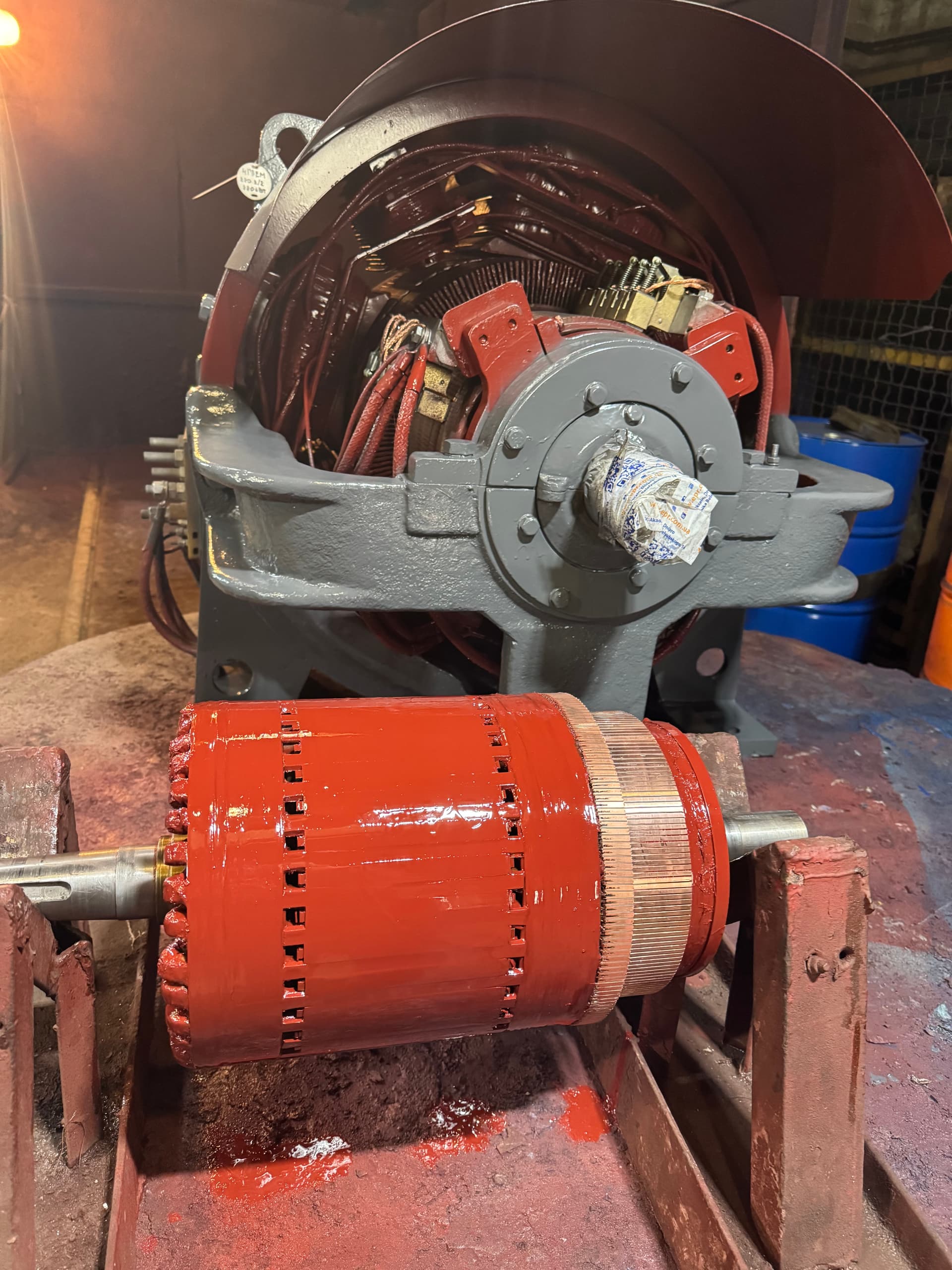
Load testing an electric motor: what is checked and why
  1. // ELEKTROPROMREMONT
  2. Load testing

Load testing an electric motor: what is checked and why

In the list of post-repair motor tests, the load test usually comes last — after the mechanical inspection, insulation resistance measurement, interturn tests, the high-voltage test and the no-load run. This article does not repeat that whole list; it looks in depth at the load test specifically — at what it reveals that no other test does.

A motor that spins perfectly at no load — quietly, with normal current and low vibration — is still not proof of a good repair. Some defects stay electrically and mechanically silent without load and only appear once rated current is flowing through the windings and the shaft is actually transmitting torque.

A load test is typically called for:

  • after a capital repair or rewind of a medium or large motor;
  • before commissioning the motor at the customer’s site;
  • whenever the acceptance-test program or the customer’s specification requires it directly;
  • for critical or high-power machines, where the cost of a failure is high;
  • if the pre-repair complaint was specifically load-related — heating, speed droop, sparking, vibration.

This article does not repeat the general list of post-repair tests — that is covered in the overview “What Tests a Motor Goes Through After Repair.” Here we look in depth at the load test itself: what it requires, how long it takes, and which faults only it can reveal.

Why a load test is needed once the motor has already passed a no-load run

At no load, the windings carry only magnetizing current plus what covers friction and windage losses — a fraction, sometimes an order of magnitude less, of the rated working current. The shaft transmits no useful torque. A large share of the electrical, thermal and mechanical processes that actually determine whether a motor is fit for service simply never reach full strength at no load.

A motor can therefore spin perfectly unloaded and still carry a hidden fault that only shows up in service:

  • weak commutation in collector machines — sparking is barely there at low armature current and becomes noticeable only at rated current;
  • insufficient torque — the motor turns freely but cannot hold the rated load without excessive slip or speed droop;
  • excessive heating — copper losses scale with the square of the current, so the real thermal regime only appears at working current;
  • mechanical instability — parts that hold in place at no load can shift or start vibrating under real torque and the magnetic forces of full current;
  • bearing loading changes in both direction and magnitude — radial and axial forces under real torque differ from those in free rotation.

A load test is the only way to confirm not that the motor turns, but that it does the job it is rated for, in the declared duty.

What is checked during a load test

The exact scope depends on the type of machine and the test program, but the basic set almost always covers current, heating, speed, vibration and noise, plus commutation for collector machines.

Load current

Current is measured on every phase (for AC motors) or in the armature and field circuits (for DC machines) at the actual or rated load and compared against the nameplate value for that load point, corrected for the actual supply voltage. Phase-current balance is also rechecked under load: an asymmetry invisible at no load can grow considerably once loaded.

Heating

Winding, bearing, frame and coolant temperatures are tracked throughout the load run, not just at the end. What matters is not a single reading but how the temperature rises over time and when it reaches a stable level. This is covered in depth in the next section.

Speed under load

Speed under load is compared against the no-load speed and the nameplate curve. For an induction motor, slip at rated load is checked against the nameplate value, corrected for actual voltage and frequency. For a DC motor, how much speed droops under load depends on the type of excitation — covered in a dedicated section below.

Vibration and noise under load

Vibration and noise are measured both at no load and under load, and the two results are compared. Loading brings electromagnetic forces proportional to the square of the current and a reaction torque on the frame and mounts — so defects that stay mechanically or electromagnetically silent unloaded can show up right here.

Commutation quality (collector machines)

For DC motors and other collector machines, brush sparking is checked separately under load. At no load, armature current is small and commutation almost always looks acceptable — which is exactly why a load test is the main way to catch marginal or hidden defects in the commutation system. Covered in more depth in a dedicated section below.

Thermal behavior and how long the test runs

An electric machine does not heat up instantly: the heat generated by its losses accumulates in the mass of the winding, core and frame while cooling removes it at the same time. How fast this plays out is set by the machine’s thermal time constant, which depends on mass, heat capacity and cooling effectiveness. In small motors that time constant can be tens of minutes; in large ones, several hours.

That is why a load test has no single fixed duration that fits every motor. A small machine can reach a stable thermal state after 30–60 minutes under load. A large enclosed machine with a heavy core or liquid cooling can need several hours of continuous running, and for some large machines, a full shift.

In practice, stabilization is judged by how the temperature behaves, not by the clock: readings are taken at regular intervals — typically every 20–30 minutes — and the temperature is treated as effectively stable once the rise between several consecutive readings becomes negligible, rather than once some predetermined time has elapsed.

A shortened load test is a common mistake that saves time but not information. A large machine’s heating curve almost always looks flat and “safe” early on, whether or not a hidden defect is present — the difference only becomes visible closer to thermal saturation. A winding defect, a locally reduced conductor cross-section, poor ventilation or a blocked cooling path can stay invisible for the first 20–30 minutes and only fully reveal itself after several hours of running.

The key criterion is not one final number but the whole series of readings: temperature has to reach a stable level below the limit for the machine’s insulation class. If temperature keeps climbing with no sign of leveling off within a reasonable test duration, that is itself a red flag, covered separately below.

Load-test specifics for DC motors

In a DC motor, how speed behaves under load depends directly on the type of excitation, so the nameplate speed-versus-load curve has to be compared against the specific machine’s excitation scheme.

Excitation typeSpeed behavior under loadWhat this affects
Shunt (parallel)Small speed droop — a relatively stiff mechanical characteristicSuits drives that need stable speed across a wide load range
SeriesSpeed falls sharply as load rises; at light load, speed rises just as sharplyHigh starting torque; a dangerous runaway if it operates unloaded or the mechanical coupling breaks
CompoundA characteristic in between — depends on cumulative or differential compoundingA compromise between speed stability and starting torque

During the test the actual speed-versus-load curve is recorded and compared against what is expected for that excitation type. A speed droop noticeably larger than expected can point to excessive armature-circuit resistance — poor connections, bad brush contact, excessive armature reaction without adequate compensation — and, for shunt machines, to a field-circuit problem that changes the flux specifically under load.

Commutation under load

At no load, armature current is small, so commutation almost always looks acceptable even with a hidden defect present. As load rises, so does the current that has to be commutated in every armature coil per revolution — and with it, the demands placed on the commutation system. A marginal defect that does not show at all at no load — a slightly shifted brush rocker, weakened interpoles, a partial interturn short in an armature coil — crosses the threshold at a certain load level, beyond which sparking becomes visible and grows with the load.

Sparking is therefore checked not once but at several load levels, including rated load, and, where the technical requirements call for it, during a brief overload run under a defined program.

Common load-test setups

The loading method depends on the motor’s power, the equipment on hand, and whether the test is run in the repair shop or at the customer’s site.

A brake stand, dynamometer, or eddy-current brake

A mechanical, hydraulic or eddy-current brake coupled to the motor shaft through a torque sensor lets the load be set smoothly and precisely from zero up to rated and beyond. It is the most controllable method — torque, and so load, can be set with high precision and held steady for as long as needed. The limitation is the brake’s own power and heat capacity: a stand large enough for a very big machine is not always available.

Loading through the actual driven mechanism on site

The motor is connected directly to the pump, fan, compressor or other machine it is meant to drive. This gives the most realistic picture — actual inertia, the real coupling, genuine ventilation and mounting conditions. The drawback is that the load usually cannot be precisely dialed in or pushed to exactly rated or overload level: it is set by the driven machine’s own characteristic, not by the test program.

Back-to-back (mutual) loading with a second machine

For large machines, when a brake stand of adequate power is not available or would not be economical, back-to-back loading is used: two identical or similar machines are mechanically coupled shaft-to-shaft, one running as a motor and the other as a generator. Electrical power partly circulates between them, so the supply mainly only has to make up the combined losses of both machines rather than the full rated power of one. This makes it possible to run a genuine test at rated torque, current and heating on a large machine while drawing far less power from the mains than loading it with a dedicated brake of the same rating would require. The method needs a second compatible machine and a suitable electrical arrangement, which is why it is typically reserved for large machines where a dedicated load bank is not a practical option.

How to interpret load-test results

Interpreting the results correctly means comparing measured values against the nameplate data and the design calculation — not simply noting that “the motor runs and does not stop.”

  • current at each load point is compared against the nameplate value for that load, corrected for the actual supply voltage;
  • temperature is compared against the limit for the machine’s insulation class and, where available, against the pre-repair baseline;
  • speed or slip under load is compared against the nameplate characteristic for that machine type and excitation scheme;
  • vibration under load is compared both against the no-load result and against the allowable levels for the applicable machine class;
  • for DC motors, the measured speed-versus-load curve is compared against what is expected for that excitation type;
  • the trend across the whole run is judged, not just the final reading — whether the readings stabilize or keep climbing is far more informative than any single number.

A motor that turns, produces some torque, and does not stop can still be defective — with weak commutation, marginal insulation margin, or an undersized winding conductor after a rewind. Compliance can only be shown by comparing numbers against the nameplate and the design calculation, not by a subjective “it runs fine.”

A verdict on repair quality comes from comparing measured parameters against the nameplate values and the design calculation — not from the mere fact that the motor turns under load.

Signs that only appear under load

The five signs below are exactly what a load test is run to catch — none of them practically shows up in a no-load run.

Symptom under loadLikely causeWhat to check
Current above nameplate at rated loadWinding error, core damage, mechanical dragTurn count, connection scheme, air gap, hand rotation
Temperature never stabilizesInadequate ventilation, undersized conductorFan, direction of rotation, winding data
Speed droop larger than expectedExcess armature-circuit resistance, rotor defectContact connections, field circuit, rotor
New vibration or noise under loadLoose parts, misalignment, bearing defectMounting, coupling, bearings
Brush sparking under loadShifted neutral, weak interpoles, armature defectRocker, interpoles, armature winding
01

Current above nameplate at rated load

At rated mechanical load, the measured current — line current or armature current — noticeably exceeds the nameplate value for that load point, even after correcting for the actual supply voltage. Causes include a wrong turn count or connection after a rewind, higher losses from core damage, or mechanical drag demanding more electromagnetic torque than the design allows for. At no load, magnetizing current dominates, and the same winding error may barely move it — which is exactly why this defect only shows under load.

02

Temperature that never reaches a stable level

Instead of gradually leveling off, temperature keeps rising over time even at a constant load — a sign that the machine’s losses in that regime exceed what the cooling system can remove. Possible causes: blocked or misdirected ventilation (including reversed airflow from a rewind that changed rotation direction), an undersized conductor cross-section from a repair error, or extra losses from insulation or core damage. A short run under load will not reveal this — the heating curve usually looks perfectly normal in the first few minutes regardless of whether a hidden defect is present.

03

Speed droop under load larger than expected

Measured speed at rated load falls more than the nameplate characteristic predicts. In an induction motor this shows up as excess slip — a possible cause being a rotor-cage defect, a broken bar, or reduced terminal voltage under load. In a DC motor it can point to excess armature-circuit resistance, poor brush contact, excessive armature reaction without adequate compensation, or, in shunt machines, a field-circuit problem. At no load, speed sits close to synchronous or no-load speed regardless of these defects, so this sign needs load to appear.

04

Vibration or noise that appears or worsens only under load

Operating under load adds electromagnetic forces proportional to the square of the current and a reaction torque on the frame, feet and coupling — forces that are absent or much weaker at no load. New or worse vibration specifically in this regime points to: loose winding or core laminations shifting under magnetic force; coupling misalignment that only shows up once real torque is transmitted; a bearing defect that only “speaks up” under radial or axial load; or a resonance excited at the operating frequency and force amplitude that only exist under load.

05

Brush sparking that appears or intensifies under load

In collector machines, at low armature current with no load, commutation almost always looks acceptable. As load rises, so does the current that has to be commutated in every armature coil, and with it the strain on the commutation system. A marginal defect — a slightly shifted brush rocker, weakened or faulty interpoles, a partial interturn short in an armature coil — crosses a threshold at some current level, beyond which sparking becomes visible and grows with the load. A detailed breakdown of the causes of brush sparking is covered in a dedicated article.

Where a load test fits in the acceptance-test program

No single test proves an electrical machine is fully sound on its own — each closes off its own part of the picture. Insulation resistance and the high-voltage test statically confirm that the insulation can safely withstand the working and test voltages. The no-load run confirms basic mechanical soundness, correct rotation direction, and the absence of gross electrical or mechanical defects. But only the load test confirms that the motor can actually do the work it is rated for, under real electromagnetic and thermal stress.

  • insulation resistance and the high-voltage test — confirm the insulation’s electrical strength statically, before any working load is applied;
  • the no-load run — confirms basic rotation, direction, and the absence of obvious defects at minimal current;
  • the load test — confirms rated operating parameters, thermal behavior, and mechanical stability at real torque and current.

That is why a load test is the logical final step of an acceptance-test program — the most realistic check before handover, bringing together in one operating regime everything the static and no-load tests checked separately. Skipping it after a capital repair, a rewind, or the replacement of a rotor, bearings, or a brush assembly leaves exactly the piece of uncertainty unresolved that no other test can close.

Frequently asked questions

Can a load test be skipped?

For minor, non-critical repairs of a small motor, a no-load run is sometimes considered sufficient. For a capital repair, a rewind, and for high-power or critical machines, a load test is strongly recommended, and an acceptance-test program often makes it mandatory — it is exactly what catches defects that stay hidden at no load.

How long does a load test take?

From 30–60 minutes for small machines to several hours, or even a full shift, for large machines with a long thermal time constant. The benchmark is not a fixed duration but temperature reaching a stable level: readings are taken every 20–30 minutes until the change between them becomes negligible.

What if the motor only overheats under load?

That is not an immediate verdict of a bad repair. First check the cooling system’s performance under the real losses that appear at load, the winding data and connections after a rewind, the fan’s rotation direction, and whether the mounting conditions match the design — then rerun the test with the load raised in stages under supervision. The outcome may call for partial rework rather than a full rewind.

How is a load test different from a no-load run?

At no load, the machine carries only magnetizing current plus what covers friction and windage losses, and the shaft transmits no useful torque. Under load, current, heating, electromagnetic forces and bearing loading match the real operating regime — which is exactly why some defects only appear here.

What counts as “rated load” for the test?

It is the operating point from the machine’s nameplate — rated power, voltage, current and speed. In practice the load is often raised in stages, for example 25, 50, 75 and 100 percent of rated, with parameters checked at each step. A brief overload above rated is only run under a separate, explicitly defined program.

Can a load test be run on site instead of on a test bench?

Yes, and for commissioning it is often the only practical option — the motor is connected to the actual driven mechanism. But where possible, a bench test before installation is valuable precisely because it isolates the motor from outside causes — a mismatched load characteristic, misalignment introduced during installation, or supply issues at the site — that could otherwise easily be mistaken for a fault in the motor itself.

EPR (Elektropromremont) services

EPR (Elektropromremont) carries out full load testing as the final stage of acceptance testing after repair, rewinding and capital overhaul of AC and DC electrical machines.

The loading method is chosen for each machine — a brake stand, connection to the customer’s actual driven mechanism, or back-to-back loading for large machines. The scope of work includes:

  • agreeing on the loading method and level for the specific machine;
  • measuring current, voltage, speed and power at each load step;
  • monitoring winding, bearing and frame temperature through to thermal stabilization;
  • measuring vibration and noise under load against the no-load result;
  • checking commutation and brush sparking for collector machines;
  • issuing a test report comparing measured parameters against the nameplate data.

Conclusion

A no-load run confirms that a motor spins correctly and without gross defects. But only a load test confirms that the motor can reliably do the job it is rated for — at rated current, with acceptable heating, stable speed, without excessive vibration, and, for collector machines, without dangerous sparking.

The most realistic check of repair quality is a load test run through to thermal stabilization — not a short trial start.

Important disclaimer

This material is for informational purposes. The values, diagnostic methods, scope of work and recommendations given here are general and do not replace the manufacturer’s technical documentation. The final decision for a specific machine is made from its own diagnostics and inspection, taking into account its type, power, design, duty, operating history and applicable standards.

Need to test a motor under real load?

We run load testing of an electric motor after repair — checking current, heating, speed, vibration and commutation, with a full test report.

Get a consultation