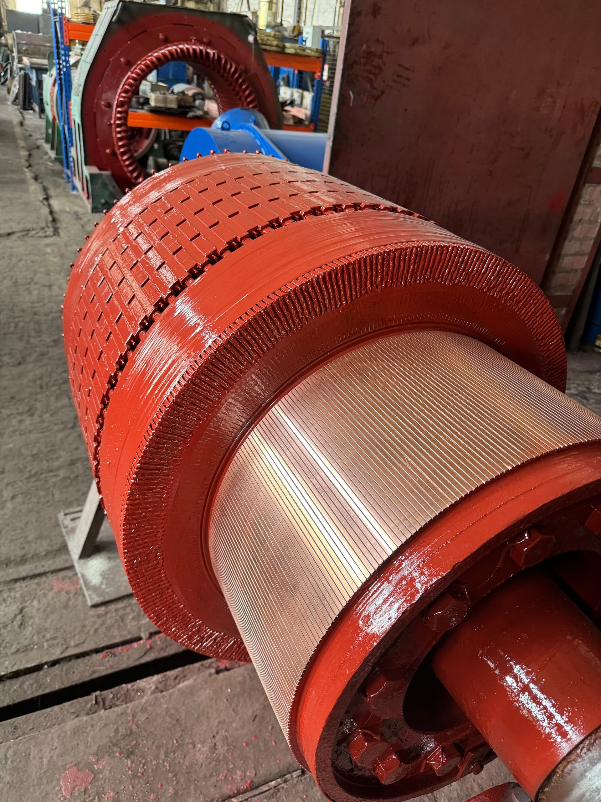
A DC motor is an electrical machine that converts direct-current electrical energy into mechanical energy through the interaction of current in the armature winding with the magnetic field of the poles, with the commutator continuously reversing the direction of that current.
Although most industrial drives today are built around induction motors and variable-frequency drives, DC machines remain in service wherever a very high starting torque, deep and smooth speed control over a wide range, or precise torque control is required — in rolling mills, traction drives, cranes, excavators and the exciters of synchronous machines.
DC motors and the closely related DC generators are used, among other things, in:
rolling mills at metallurgical plants;
traction drives of electric locomotives, diesel-electric locomotives and mine transport;
cranes, hoists and excavators;
drives requiring deep speed control — winders and unwinders;
exciters for synchronous generators and motors;
welding generators;
laboratory and test equipment;
certain types of electric vehicles and special machinery.
The main reasons DC machines are still used alongside modern induction drives are:
inherently high starting and overload torque;
a simple, smooth way to control speed over a wide range;
a linear relationship between torque and armature current that is convenient for precise control;
the ability to control speed both below and above the rated value;
decades of operating experience on demanding industrial equipment;
a large installed base of machines that it is more economical to repair than to replace.
At the same time, a DC motor is a substantially more complex machine than a squirrel-cage induction motor.
Its service life depends on the condition of several interdependent assemblies:
the magnetic system — the yoke, the main and interpole poles;
the armature — its core, winding and commutator;
the brush assembly;
the bearings and shaft;
the ventilation and cooling system.
A repair that restores only one of these assemblies is not enough — the commutator, the armature winding and the bearings should be treated as parts of a single electromechanical system.
01
Short answer
A DC motor is an electrical machine in which direct current in the armature winding interacts with the stationary magnetic field of the poles, while the commutator and brushes continuously reverse the current direction in the rotating armature conductors so that the electromagnetic torque always acts in the same direction.
In the most general terms, a DC motor works as follows:
01Direct current is fed into the armature winding through the brushes and commutator.
02The armature winding conductors sit within the magnetic field of the main poles.
03A force acts on every current-carrying conductor in the magnetic field, producing electromagnetic torque.
04The armature begins to rotate.
05As it rotates, the commutator switches the current in the armature conductors so the resulting torque keeps its direction.
06At the same time, a back electromotive force is induced in the armature winding that grows with rotational speed.
The main types of DC motor by method of excitation are:
series-wound;
shunt-wound;
separately excited;
compound-wound;
permanent-magnet.
Each type has its own torque-speed characteristic and its own typical field of use, covered below.
02
Main parts of a DC motor
A DC motor consists of a stationary magnetic system (the stator) and a rotating armature, linked through the air gap, together with a brush assembly that provides the electrical contact between the stationary and rotating parts of the machine.
The main assemblies are:
the frame (yoke);
the main poles with the field winding;
the interpole (commutating) poles;
the armature — core, winding and commutator;
the brush assembly with brush holders and rocker;
the shaft and bearings;
the end shields;
the ventilation system;
the terminal box and leads.
The frame (yoke)
The frame is the motor’s outer housing and, at the same time, part of the magnetic circuit.
It performs several functions:
closes the magnetic flux path between poles;
carries the main and interpole poles;
provides the mechanical rigidity of the structure;
takes the reaction load from the mounting feet or flange;
often serves as the mounting point for the end shields.
Frames are cast from steel or cast iron, or, in large machines, welded from structural steel plate; the material and wall thickness are chosen to give the cross-section the flux needs without excessive saturation.
Main poles and the field winding
The main poles are bolted to the frame and produce the machine’s main magnetic flux.
Each main pole consists of:
a pole core built up from laminated or solid steel;
a pole shoe, which shapes the field distribution across the air gap;
a field coil wound around the core.
The field winding can be supplied from the same source as the armature (shunt- or series-wound motors), from a separate source (separate excitation), or combine a series and a shunt coil on the same pole (compound excitation).
Interpole (commutating) poles
Interpoles are mounted between the main poles, precisely on the machine’s geometric neutral.
Their winding is connected in series with the armature circuit, so the field they produce is proportional to the load current.
Their purpose is to compensate for the reactance voltage induced in the coil undergoing commutation, thereby keeping commutation sparkless across a wide load range.
Reversed polarity, an open circuit, or an interturn short in an interpole winding after a repair is one of the most common causes of heavy brush sparking even when the commutator itself is in good condition.
The brush assembly
The brush assembly consists of the brushes, the brush holders and the rocker they are mounted on.
Spring-loaded brushes pressed against the commutator surface provide the sliding electrical contact between the stationary supply and the rotating armature.
The rocker lets the brushes be set precisely on the neutral axis and, when needed, allows the whole brush assembly to be rotated together during adjustment.
Shaft, bearings and ventilation
The shaft transmits the armature’s torque to the driven machine and carries the radial and axial loads through bearings fitted in the end shields.
Cooling is provided by a shaft-mounted fan, by an independently driven forced-ventilation fan, or, in high-power machines, by air-to-air or air-to-water heat exchangers — the choice depends on the motor’s power, duty cycle and the dust and moisture levels expected in the installation.
03
The armature: core, winding and commutator
Armature core
The armature core is built up from thin electrical-steel laminations insulated from one another with varnish or an oxide film to limit eddy-current losses, since, unlike the main poles, the armature core is continuously remagnetized as it rotates.
The armature winding is laid in slots cut into the core, and the laminated stack itself is pressed onto the shaft or onto a hub.
Armature winding
The armature winding is built as either a lap (parallel) winding or a wave (series) winding, with its ends connected to the corresponding commutator segments.
The choice of winding type depends on the machine’s rated current and voltage:
lap windings are used in machines rated for high current and comparatively low voltage;
wave windings are used in machines rated for high voltage and lower current.
Coil sides are held in the slots with wedges or bands, and the end windings with binding wire or glass tape, since they experience considerable centrifugal force in operation.
Commutator
The commutator is made up of copper segments, insulated from one another and from the shaft by mica or another heat-resistant dielectric.
Each segment is connected to the corresponding armature coil, so the commutator is effectively a mechanical switch that, together with the brushes, acts as a rotating rectifier: it converts the alternating current in the armature coils into direct current in the external brush circuit.
After the commutator surface is turned, the inter-segment insulation must be recessed below the copper — an operation called undercutting; if the mica stays flush with or stands proud of the copper, the brush loses stable contact, which causes vibration and sparking.
04
Operating principle
Current and the magnetic field
A current-carrying conductor placed in a magnetic field experiences an electromagnetic force whose direction is given by the left-hand rule and whose magnitude equals the product of flux density, conductor length and current.
Because the armature conductors are distributed around the circumference under main poles of opposite polarity, the forces acting on them combine into a net rotating electromagnetic torque applied to the armature.
The commutator’s role: commutation
As the armature rotates, each coil passes in turn under poles of alternating polarity, so the current in it must periodically reverse — this is exactly what the commutator and brushes accomplish together.
The moment a brush bridges two adjacent segments, the corresponding coil is briefly short-circuited, and the current in it must fall to zero, reverse, and rise to its new value in the opposite direction — this process is called commutation.
The interpoles, whose winding carries the armature current, induce a compensating electromotive force in the coil being commutated that helps the current change in time; if this compensation is inexact, sparking appears under the brush.
Back electromotive force (armature EMF)
As the armature turns in the magnetic field, an electromotive force is induced in its winding that opposes the applied voltage — the so-called back EMF, or armature EMF.
Its magnitude is approximately proportional to the product of the pole flux and the rotational speed:
E = k · Φ · n
where:
E is the armature back EMF;
k is the machine’s design constant;
Φ is the pole flux;
n is the rotational speed.
The voltage at the armature terminals equals the back EMF plus the voltage drop across the armature circuit resistance:
U = E + I · R
where I is the armature current and R is the combined resistance of the armature winding and brush contact.
Torque and how speed depends on load
The motor’s electromagnetic torque is approximately proportional to the product of the pole flux and the armature current:
M = kt · Φ · I
These relationships give the DC machine its basic mechanical characteristic: speed rises with applied voltage, falls as load increases (because the I · R drop grows), and rises as the pole flux is reduced — these three dependencies are exactly what the practical speed-control methods described below rely on.
05
Motor types by method of excitation
How the field winding is connected to the armature circuit determines the motor’s torque-speed characteristic and, with it, the applications it suits.
Series-wound motor
The field winding is connected in series with the armature, so the magnetic flux depends on the same current that produces torque.
This gives the motor its characteristic properties:
a very high starting torque;
torque that rises roughly with the square of the current on the unsaturated part of the curve;
speed that rises sharply as load falls and can reach dangerous values if the load is fully removed — the so-called runaway condition.
A series-wound motor must never be run unloaded or with a disconnected drive link — losing the mechanical load with power still applied can drive the speed to a destructive runaway.
Because of its high starting torque, this type is traditionally used in traction drives — electric locomotives, trolleybuses, cranes and hoisting mechanisms — wherever a large torque at standstill matters most.
Shunt-wound motor
The field winding is connected in parallel with the armature (or, in a separately excited motor, fed from a separate source at the same rated voltage).
The magnetic flux is nearly independent of the armature load, so this motor’s speed stays almost constant over a wide load range — a characteristic close to a hard, or stiff, curve.
Shunt and separately excited motors are used wherever a stable speed and precise control are required — in metal-cutting machine tools, feed drives, and certain pumps and fans with special control requirements.
Separately excited motor
Structurally identical to a shunt motor, but the field winding is fed from an independent DC source rather than from the armature terminals.
This allows the field current and armature voltage to be controlled independently, which is exploited in deep, precise speed-control systems built around a Ward Leonard set or a controlled rectifier.
Compound-wound motor
Has two windings on each main pole: a series winding and a shunt winding.
Depending on whether their magnetic fluxes add or subtract, two variants are distinguished:
cumulative compounding, where the fluxes add — the resulting curve combines the series motor’s higher starting torque with the shunt motor’s speed stability;
differential compounding, where the fluxes subtract; rarely used in practice because the resulting curve becomes unstable at heavy load.
Cumulatively compounded motors are used in drives that need both an elevated starting torque and a limited no-load top speed — for example, in certain crane and rolling-mill mechanisms.
Permanent-magnet motor
The main poles are built from permanent magnets rather than a field winding, so the magnetic flux is essentially constant across the whole load range.
Advantages include a simpler construction, no field losses, and compact size; the drawback is that speed cannot be raised by field weakening, and the magnets risk partial demagnetization under heavy overload or overheating.
These motors are common in low- and medium-power drives — power tools, gate and valve actuators, small servo drives and certain electric vehicles.
06
Speed control
One of the main reasons DC machines are still used alongside variable-frequency induction drives is how simply and how deeply their speed can be controlled.
Three main methods are used in practice, and they are often combined.
Field weakening
Reducing the field current lowers the magnetic flux and, with the armature voltage held constant, raises the rotational speed.
This method extends speed above the rated value, but it reduces the available torque, since torque is proportional to both flux and armature current — hence this range is called the constant-power zone, as opposed to the constant-torque zone obtained with armature voltage control.
Armature voltage control
Varying the voltage applied to the armature while keeping the rated field flux constant gives smooth speed control from zero up to rated speed with practically no reduction in available torque — the constant-torque zone.
Historically the voltage was controlled with a Ward Leonard motor-generator set; modern installations use controlled thyristor or transistor DC converters instead.
Resistance control
A resistor added in series with the armature circuit lowers speed by increasing the I · R voltage drop, but it wastes significant energy in the resistor and is a less precise, less efficient method.
Today, resistance control is mostly used to limit starting current while the motor accelerates rather than as the primary means of running-speed control.
Combined control
In practice, armature voltage control (for speeds from zero to rated) is most often combined with field weakening (for speeds above rated), giving a wide control range with minimal energy loss.
07
Key characteristics and nameplate data
A DC motor’s nameplate typically lists:
Parameter
What it shows
Rated armature voltage
The design supply voltage for the armature winding
Rated field voltage
The supply voltage for a separately excited field winding
Rated armature current
The maximum continuously permissible armature current
Rated power
The mechanical power at the shaft in the rated duty
Rated speed
The rotational speed at rated voltage, current and flux
Method of excitation
Series, shunt, separate, compound, or permanent magnet
Duty type
S1–S10, by load duration and pattern
Insulation class
The maximum permissible winding temperature rise
IP rating
Protection against contact, dust and moisture
Direction of rotation
The permitted direction, or whether reversal is allowed
Beyond nameplate data, assessing a specific machine’s condition and repairability also calls for knowing:
the number of poles and parallel paths in the armature winding;
the armature winding type — lap or wave;
whether a compensating winding is fitted, and its layout;
the number and diameter of the commutator segments;
the grade of brush fitted;
the permissible overload, by torque and by duration.
08
Typical applications
Traction drives
Series- or compound-wound DC traction motors are traditionally used in electric and diesel-electric locomotives, trams and mine haulage equipment thanks to their inherently high starting torque and their ability to withstand significant short-term overloads when starting off and climbing grades.
Rolling mills
In metallurgy, separately excited DC motors have long remained the drive of choice for the roughing and finishing stands of rolling mills, since they allow speed and torque to be controlled accurately and quickly in a cyclic, reversing duty with frequent overloads.
Cranes, hoists and excavators
Crane and excavator drives call for a motor that tolerates frequent starts, reversals and stalls, along with the high torque overload capacity typical of series- and compound-wound machines.
Generators and exciters
DC machines are also used as generators — power sources for the excitation systems of synchronous generators and motors, welding sets, plating lines and laboratory equipment that need a controllable DC voltage.
Precision-controlled drives
Separately excited and shunt-wound motors are used in metal-cutting machine tools, in winders and unwinders in the textile and paper industries, and in other equipment where smooth speed control over a wide range at constant torque matters.
09
Advantages and disadvantages
Advantages of DC machines:
a simple, smooth way to control speed over a wide range;
high torque overload capacity;
a linear torque-current relationship that suits precise drive control;
inherently high starting torque in series- and compound-wound motors;
decades of accumulated operating experience on demanding industrial equipment.
Disadvantages
the commutator and brushes form an assembly that needs regular maintenance;
lower maximum speed and power density than an induction machine of the same frame size;
sparking, and brush and commutator wear, when commutation is disturbed;
higher manufacturing and repair cost due to the more complex armature;
sensitivity to contamination, moisture and explosive atmospheres because of the exposed brush-commutator assembly;
the risk of a dangerous runaway in a series-wound motor if it loses its load.
10
Overview of typical faults
Below is a brief overview of the most common faults in DC machines; each is covered in more depth in a dedicated article.
01
Brush sparking and flashover
Sparking results from disturbed commutation — a misaligned rocker, a faulty interpole, a dirty or eccentric commutator, overload, or the wrong brush grade; left undiagnosed, heavy sparking can escalate into a flashover, a powerful arc across the commutator surface that destroys segments and brush holders.
02
Brush and brush holder wear
Accelerated brush wear is usually tied to incorrect spring pressure, a brush sticking in its holder, the wrong material grade, or a contaminated commutator surface; length, free movement in the holder, and even wear across all brushes of one polarity should all be checked.
03
Armature interturn short circuits
Caused by aged or mechanically damaged conductor insulation, overheating, moisture or vibration; it shows up as localized heating in one coil, characteristic sparking at the same point every revolution, and a deviation on a surge (impulse) test of the winding.
04
Faults in the main or interpole field windings
An open circuit, an interturn short, or a breakdown to frame in a field or interpole winding alters the flux and disturbs commutation; an interpole fault often masquerades as "ordinary" brush sparking and only shows up under a targeted check.
05
Bearing wear
Produces increased noise and vibration, armature run-out relative to the poles, and, as a result, an uneven air gap and additional sparking; timely bearing replacement and lubrication checks are among the cheapest preventive measures available.
06
Overheating
Can be caused by overload, poor ventilation, contaminated windings, an interturn short, or the wrong duty cycle; prolonged overheating accelerates insulation aging and eventually leads to breakdown.
07
Vibration
The most common causes are armature imbalance, poor alignment with the driven machine, worn bearings, commutator run-out, or a damaged fan; vibration, in turn, worsens brush-to-commutator contact and increases sparking.
11
Maintenance basics
Regular attention to the brush-commutator assembly and the mechanical parts substantially extends a DC machine’s service life and reduces the risk of an unplanned shutdown.
inspect the brushes periodically — length, condition of the working face, free movement in the holder, and the state of the flexible lead;
check the brush spring pressure and compare it across all brushes of the same polarity;
inspect the commutator surface — the colour of the patina film, contamination, burning, and any raised mica;
blow the machine out periodically with dry compressed air to clear carbon and metal dust from the inter-segment slots;
follow the manufacturer’s lubrication schedule for the bearings and never change the grease type without checking compatibility;
measure the insulation resistance of the armature and field windings periodically, especially after storage in damp conditions or a long shutdown;
log inspection results to track how brush and commutator wear progress between repairs.
12
Frequently asked questions
How is a DC motor fundamentally different from an induction motor?
In a DC motor, the magnetic flux and the armature current can be controlled independently, and the commutator mechanically switches the current in the armature coils; an induction motor is fed directly from an AC supply, its rotating field is produced by the stator’s own polyphase winding, and it has no commutator at all.
Why must a series-wound motor never run unloaded?
This motor’s flux depends on the armature current; when the mechanical load is lost, current and torque fall, the flux weakens, and speed can climb to dangerous levels — the so-called runaway condition, which can destroy the armature winding and commutator.
Which controls speed better — armature voltage or field weakening?
Armature voltage control varies speed from zero to rated with almost no loss of torque and is therefore the primary method; field weakening is used in addition to reach speeds above rated, at the cost of a lower available torque.
Is it worth repairing a commutator motor, or is replacement simpler?
In most cases repair is technically and economically sound: the armature, commutator, field coils and mechanical parts can be restored to the original winding data; replacement is usually the better option only when the laminated core or the frame itself is damaged, not the windings or commutator.
How often should brushes be checked?
The interval depends on duty and brush grade, but in practice the brushes and commutator are inspected at every scheduled maintenance visit, and out of schedule the moment sparking, unusual noise or a burning smell appears.
Why does the commutator need periodic turning?
Over time the commutator surface wears unevenly, developing run-out, grooves and burn marks; turning restores the correct cylindrical shape, after which undercutting — recessing the inter-segment insulation below the copper — is always required.
Are DC motors more sensitive to dirt and moisture than induction motors?
Yes: the exposed brush-commutator assembly is more sensitive to dust, moisture and aggressive environments than the fully enclosed winding of an induction motor, so DC machines more often need a protected or special enclosure and more frequent maintenance.
Elektropromremont, LLC performs diagnostics, repair and manufacturing of DC machine components — for traction, crane and rolling-mill motors, generators and exciters.
The scope of work includes:
inspection and fault-finding on the armature, commutator, magnetic system and brush assembly;
manufacturing and repair of the armature winding, including individual coils;
commutator manufacturing and repair, including undercutting and turning;
repair and manufacturing of main and interpole field coils;
shaft, end shield and fit repair;
dynamic armature balancing;
vacuum and vacuum-pressure impregnation of windings;
A DC motor is an electrical machine in which the commutator and brushes turn the armature’s rotation into a continuous reversal of current direction in its winding, so that the electromagnetic torque consistently acts in one direction.
How the field winding is connected to the armature determines the motor’s torque-speed characteristic — from the soft curve and high starting torque of a series-wound machine to the stiff, near-constant speed of a shunt- or separately excited machine.
A machine’s service life depends not only on the armature winding but also on the condition of the commutator, the brush assembly, the field coils, the bearings and the ventilation system — so a repair is best treated as restoring one electromechanical system, not a set of separate parts.
Disclaimer
This article is for general informational purposes. The choice of motor type, excitation scheme, speed-control method, winding data and repair technology for a specific machine should be based on the manufacturer’s documentation, the nameplate, and the results of professional diagnostics.
Important disclaimer
This material is for informational purposes. The values, diagnostic methods, scope of work and recommendations given here are general and do not replace the manufacturer’s technical documentation. The final decision for a specific machine is made from its own diagnostics and inspection, taking into account its type, power, design, duty, operating history and applicable standards.
Need your DC motor repaired?
We will inspect the armature, commutator, brush assembly and magnetic system, determine the scope of repair, and restore the machine to its original factory characteristics.