What are the main tests a motor undergoes after repair?
Insulation resistance, phase DC resistance, interturn testing, a hipot test, a no-load run, vibration, temperature, and, where needed, load testing.
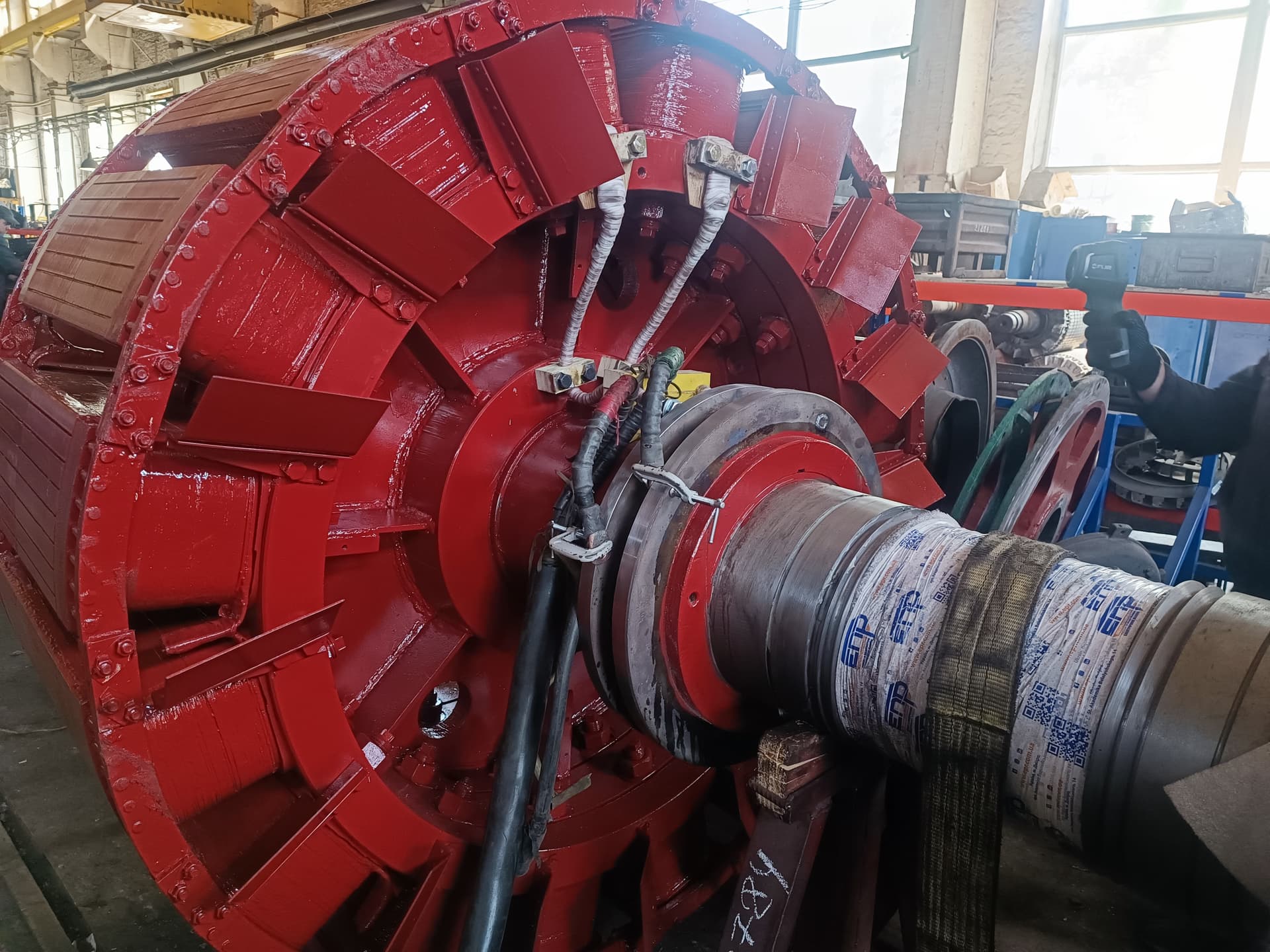
Motor testing is a set of electrical, mechanical, thermal, and functional checks that confirm a machine’s technical condition, the correctness of the repair, assembly quality, and its readiness for further operation.
Testing can be performed:
The test scope depends on the motor type, power, voltage, rotational speed, design, type of repair, manufacturer requirements, customer requirements, and the conditions of further operation. The set of tests can therefore vary substantially between machines.
After repair, a motor usually goes through the following main checks:
For large, high-voltage, and critical machines, the following can additionally be performed:
Even when a repair is done well, before returning the motor to service it must be confirmed that:
Without this, it’s impossible to objectively judge repair quality.
It’s important to distinguish two stages. Incoming testing is performed before repair, and its goal is to record the motor’s actual condition. Outgoing testing is performed after repair, and its goal is to confirm the repair was done well and the motor is ready for service.
Comparing incoming and outgoing parameters gives far more information than a single final test.
Before disassembly, it’s worth recording the external condition, motor number, nameplate data, insulation resistance, phase DC resistance, vibration, noise, currents, heating pattern, bearing condition, and the reason for taking the motor out of service. If the motor can run safely, a short no-load test is sometimes performed before repair — this provides a baseline for post-repair comparison.
The first step is an external check. Inspect:
There must be no cracks, loose bolts, damaged cables, exposed live parts, oil traces, or foreign objects inside the machine.
Before applying voltage, check that the bearings are correctly fitted, there is proper axial float, no jamming, the rotor and fan are properly fastened, the bearing brackets are correctly positioned, sealing is intact, and fits are correct. The rotor should turn smoothly.
Before starting, the rotor is turned by hand or with a special tool, checking for friction, unusual sounds, sticking, impacts, and a sudden change in resistance. If the rotor turns unevenly, the motor should not be started until the cause is found.
One of the basic electrical tests. It checks phase-to-frame, phase-to-phase, rotor-winding-to-frame, and field-winding-to-shaft-or-frame insulation. The goal is to confirm the insulation has no hazardous leakage currents.
The result is affected by temperature, humidity, contamination, winding surface area, insulation material, and rated voltage. The result must therefore always be judged in context — the same winding can show different values at different temperatures.
For the relevant machines, the change in insulation resistance over time — the polarization index — can be assessed. It helps analyze moisture, contamination, and overall insulation condition — especially relevant for large motors, high-voltage machines, and generators.
Winding DC-resistance measurement checks phase symmetry, contact connections, winding correctness, and the absence of an open circuit. Phases U, V, and W are compared, and results should be referred to the same temperature.
If one phase has a significantly different resistance, possible causes include an incorrect turn count, a poor connection, an open parallel path, an incorrect cross-section, or a rewinding error. Even with good insulation resistance, such a machine can operate incorrectly.
For a three-phase motor, the phases must be as symmetrical as possible in DC resistance, inductance, and electrical scheme. Asymmetry can cause uneven currents, elevated vibration, overheating, and reduced torque.
After rewinding, it’s necessary to confirm correct phase start and end points, correct group sequencing, the star or delta scheme, and correct terminal wiring. A scheme error can render the motor inoperable even with fully sound insulation.
Phasing confirms the phases’ correct electrical and spatial arrangement. An incorrectly wired phase group can create a field that opposes the other coils. Signs: elevated current, a loud hum, low torque, and heating.
One of the most important tests after rewinding is the interturn test. An interturn fault may not be detected by a megohmmeter, so a surge test, phase comparison, induction methods, or special coil testers are used.
In a surge test, a short high-voltage pulse is applied to the winding, and the winding’s response is then analyzed — phases, coils, and reference signals are compared. An interturn defect changes inductance, waveform shape, frequency, and damping.
A hipot test confirms the dielectric strength of the main insulation — voltage is applied between the winding and the grounded frame. This test is often performed after rewinding, a complete repair, section replacement, or significant intervention in the insulation system.
A megohmmeter assesses insulation resistance, while a hipot test checks its ability to withstand a specified voltage without breaking down — these are different kinds of checks. Harsh tests should not be repeated uncontrollably, especially on old insulation: the level and duration must be set by the machine type, insulation condition, repair scope, and technical documentation.
Partial-discharge testing is used mainly for high-voltage machines. Partial discharges can occur inside voids, between the insulation and the core, on a section’s surface, or at the slot exit — their activity can indicate defects in the insulation system.
For high-voltage insulation, the dissipation factor (tan δ) can be measured, characterizing losses in the insulation, its overall condition, possible moisture ingress, and aging. Comparison with previous measurements is often the most valuable indicator.
If a motor was rewound after a failure, or the winding burned out badly, it’s important to check the core — damage to the interlaminar insulation can cause local heating, and after fitting a new winding, such a defect can cause a repeat failure. Inspection methods: visual inspection, ring-flux magnetization, thermal imaging, and specialized local-inspection systems.
For an induction motor, it’s important to check the bars, short-circuiting rings, welded joints, cracks, and local overheating — rotor defects may not show up in a routine stator-insulation measurement. Possible methods: visual inspection, induction testing, current analysis, thermal monitoring, vibration analysis, and special bench tests.
For a wound rotor, insulation resistance, phase DC resistance, symmetry, slip rings, turn insulation, connections, and bandages are all checked.
During a major overhaul, shaft runout, journals, fits, keyways, fillets, tapers, and threads are checked — magnetic-particle testing, ultrasonic testing, or dye-penetrant testing is used where needed.
Before start-up and during operation, ease of rotation, noise, play, temperature, lubrication, and bearing fit are all checked. After a replacement, it’s especially important to confirm the bearing isn’t over-tightened, there’s no misalignment, the correct clearance was chosen, and the amount of lubricant meets requirements.
Large and converter-fed machines can use insulated bearings — check for electrical shunting of the insulation through fastenings, sensors, lubrication lines, or metal components.
For large machines, or after bearing-assembly repair, the gap between the rotor and stator is measured — it must be adequate, uniform, and consistent with the design. Non-uniformity can indicate eccentricity, incorrect assembly, a bent shaft, or bearing problems.
After rotor repair, wound-rotor rewinding, fan replacement, shaft repair, or a change in mass distribution, balance must be checked. An unbalanced rotor can be electrically sound but mechanically unfit for service.
One of the key final tests. The motor is started without a mechanical working load. Monitored:
No-load current is very informative after a repair. Excessively high current can indicate an incorrect turn count, an incorrect scheme, core damage, a small air gap, mechanical friction, or phase asymmetry. The three phase currents are compared — a large difference can indicate a winding error, supply asymmetry, a rotor defect, or an incorrect connection.
Before handing the motor to the customer, rotation direction is checked for the given phase sequence — especially important for pumps, fans, compressors, and drives with a specific required direction. Speed is compared against the expected value: for an induction motor, it depends on grid frequency, pole count, load, and slip — an incorrect speed after rewinding can indicate an error in the pole count or the winding scheme.
Mechanical noise, electromagnetic hum, bearing noise, fan noise, and periodic impacts are all assessed. The character of the sound can point to a bearing defect, imbalance, friction, an incorrect winding, or loosened components.
Vibration is measured at specified points on the frame or bearing supports, analyzing overall level, spectrum, frequencies, phase, and dependence on speed. Vibration can indicate imbalance, misalignment, a bearing defect, mechanical looseness, a bent shaft, electromagnetic asymmetry, or a rotor defect.
During operation, the temperature of the bearings, frame, winding, cooling air, and individual components is monitored — large machines use embedded sensors.
After start-up, it’s important to observe not just the absolute bearing temperature but also its rate of rise, stabilization, and the difference between the two sides. A rapid temperature rise can indicate an incorrect fit, misalignment, lubrication problems, or excessive axial load.
A thermal camera reveals local overheating, asymmetry, hot connections, and uneven cooling — especially useful during load testing.
For motors with forced ventilation, air direction, fan output, duct cleanliness, flow sensors, and filters are all checked. For liquid cooling — tightness, flow rate, inlet/outlet temperature, and the absence of leaks.
Gives the fullest picture of the motor’s real parameters. Current, voltage, speed, torque, power, efficiency, heating, vibration, and noise are all monitored.
Some defects only show up at high current — for example, a rotor-cage defect, a poor solder joint, a loosened connection, winding overheating, insufficient ventilation, or mechanical instability. For critical machines, load testing therefore provides far more information than a no-load test.
Load can be created using a loading generator, a second motor, an electromechanical test bench, a braking machine, or mutual loading of two machines. In mutual loading, two electrical machines are mechanically coupled — one runs as a motor, the other as a generator; energy partly circulates between them, and the grid mainly compensates the losses. This allows large machines to be tested with lower test-bench power consumption.
Torque can be determined with a dynamometer test stand, a strain-gauge sensor, calculation from other parameters, or a special loading machine. Electrical power is determined from voltage, current, and power factor; mechanical power from torque and rotational speed — this allows efficiency to be assessed.
Efficiency shows what fraction of the input energy is converted into useful mechanical power. Losses include copper losses, iron losses, mechanical losses, windage losses, and stray losses.
Heat run test: the motor runs under a specified load for a set time or until thermal stabilization, while winding, bearing, frame, and coolant temperatures are monitored. The goal is to confirm the machine can operate in the required regime without overheating.
For certain machines, a brief overload above the rated value can be applied, checking overload capacity, commutation, mechanical strength, and current behavior — performed only under an appropriate program.
For a DC motor, the commutator, brushes, commutation, neutral position, sparking, interpoles, and compensating winding are additionally checked. Commutation is checked at no load, under different loads, and at varying speed, assessing sparking, brush condition, heating, and contact uniformity.
For traction machines, operation at different speeds, commutation under high current, reversal, generator mode, braking, speed-sensor operation, and the forced-cooling system can additionally be checked.
Checking a high-voltage motor can include insulation resistance, the polarization index, tan δ, partial discharge, a hipot test, section checks, core inspection, temperature measurement, and vibration.
Modern motors can have Pt100, PTC, thermocouple, speed, encoder, vibration, flow, and leak sensors. After repair, their integrity, correct wiring, and signal correctness must be confirmed.
For motors with a variable-frequency drive or a servo system, the encoder is a critical element — mechanical mounting, clearance, signal, direction, pulse count, and channel phasing are all checked.
For certain rotors, a check at a speed above the operating speed may be required — the goal is to confirm the mechanical strength of the rotating parts. Especially relevant for high-speed motors, traction machines, generators, and commutator armatures. Such a test requires a specially guarded test bench.
For enclosed or cooled machines, the tightness of the frame, heat exchanger, water channels, and seals is checked — especially important if the repair involved welding, removing a cooler, or repairing a cooling jacket.
After repair, the operation of thermal protection, bearing sensors, emergency shutdown, and alarms can be checked. This matters because even a sound motor can be damaged if the protection system doesn’t work.
In practice, the process can be structured like this:
A well-prepared report can include:
Test reports build a history for a specific motor. Next time, insulation resistance, no-load current, vibration, temperature, and phase DC resistance can all be compared — the trend often matters more than a single absolute value.
What not to do:
A motor is simultaneously an electrical, magnetic, mechanical, and thermal system, so no single test can confirm complete soundness. Good insulation resistance doesn’t rule out an interturn fault, an open parallel path, or incorrect phasing. Normal no-load current doesn’t rule out a rotor defect that will show up under load, or overheating during extended operation. Low vibration doesn’t confirm the insulation’s dielectric strength. Tests must therefore complement each other.
Check the turn count, the scheme, phasing, the core, the air gap, and mechanical friction. Simply leaving the motor in service can let it overheat even without a heavy load.
Possible causes outside the motor: mechanical overload, low voltage, grid asymmetry, poor ventilation, frequent starts, or an incorrect frequency-converter regime. After a failure, it’s therefore important to analyze more than just the motor.
Check the fit, internal clearance, amount of lubricant, axial load, misalignment, and bearing type. A new bearing doesn’t automatically mean a correctly assembled bearing joint.
Possible causes: thermal bow, changed fits, part expansion, thermal imbalance, or misalignment. Vibration needs to be analyzed not just right after start-up but also in a stable thermal regime.
| Test result | Possible cause | What to check |
|---|---|---|
| Low insulation resistance | Moisture, contamination | Cleaning, drying |
| Phases have different resistance | The winding or a connection | Connections |
| Surge waveforms differ | An interturn defect | The coils |
| High no-load current | A winding error | Turns, the scheme |
| Uneven currents | Phase asymmetry | The winding, the supply |
| High vibration | Imbalance | The rotor |
| Vibration after warm-up | Thermal deformation | The shaft, fits |
| A bearing runs hot | The fit or lubrication | The bearing assembly |
| An unusual noise | Friction or a bearing | The mechanics |
| Incorrect speed | Pole count or frequency | The winding scheme |
| Local overheating | A winding defect | Thermal imaging |
| Insulation drops after start-up | A thermal defect | The insulation system |
| Normal at no load, defect under load | The rotor or a connection | The load test |
Insulation resistance, phase DC resistance, interturn testing, a hipot test, a no-load run, vibration, temperature, and, where needed, load testing.
No. A megohmmeter does not detect every possible defect, including interturn faults.
Yes. Rewinding changes one of the machine’s core systems, so the scheme, insulation, and operating parameters must all be confirmed.
To check the winding’s symmetry and the quality of its electrical connections.
It helps detect interturn defects.
The dielectric strength of the main insulation relative to the frame.
To check currents, noise, vibration, bearings, and rotation direction without a working mechanism attached.
Highly advisable for critical, high-power, and post-overhaul repairs, and mandatory under program in certain cases.
No. Some defects only appear under load.
To confirm the winding, bearings, and other components aren’t overheating.
It documents the actual results and provides a baseline for future comparisons.
Electropromremont LLC performs comprehensive diagnostics and testing of electrical machines after repair, rewinding, and restoration.
Depending on the machine type, the following can be performed:
The test scope for each machine is determined individually, accounting for its type, power, voltage, design, the repair performed, and the customer’s requirements.
Motor testing is the final, mandatory stage of a quality repair. It must confirm not just that the motor turns, but that it is:
A quality motor repair doesn’t end with assembly — it ends with confirming the machine’s characteristics through testing.
The most reliable approach combines static electrical tests, a mechanical check, a no-load run, vibration, temperature monitoring, and load testing, together with mandatory documentation of the results.
This material is for informational purposes. The values, diagnostic methods, scope of work and recommendations given here are general and do not replace the manufacturer’s technical documentation. The final decision for a specific machine is made from its own diagnostics and inspection, taking into account its type, power, design, duty, operating history and applicable standards.
We perform a full package of electrical, mechanical, thermal, and load tests, with a test report matched to your machine’s type and power.