What is motor vibration?
Mechanical oscillation of the housing, bearing supports, shaft and other parts while the motor runs.
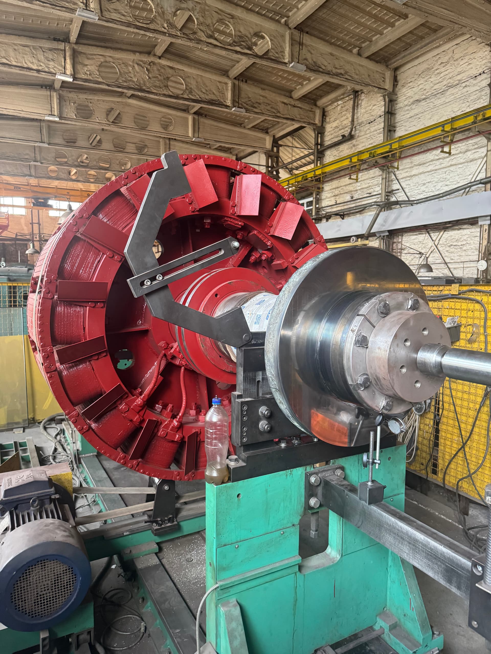
Motor vibration is the mechanical oscillation of the housing, bearing supports, shaft or other parts of the machine while it runs.
Every rotating machine has some level of vibration. It becomes a problem when it:
Vibration diagnostics lets many faults be caught before they cause a failure. The character of vibration can point to:
That is why vibration checks are one of the key elements of motor control after repair and during operation.
Motor vibration is checked with dedicated sensors and vibration analyzers. The sensor is mounted on the bearing endshield, the bearing housing, a support, or another defined measurement point. It is usually measured in three directions: horizontal, vertical and axial.
The main parameters are:
For the general condition assessment of most industrial machines the RMS value of vibration velocity is commonly used. For bearing diagnostics, acceleration and the high-frequency spectrum are often more important. Large machines with sleeve bearings may also have direct shaft vibration monitoring.
Vibration is a repeated motion of a part or structure around some average position. For example, if a motor’s bearing endshield slightly shifts left-right-up-down while it runs, that is mechanical oscillation. It can be so small that it is not visible, but a sensor can measure it.
A perfectly still rotating machine does not exist. There is always some residual imbalance, electromagnetic forces, bearing operation, fan motion, manufacturing tolerances and foundation motion. So the goal of diagnostics is not to reach absolute zero, but to determine whether the level is acceptable, whether it is stable, and whether there are signs of a specific fault.
Vibration can be roughly divided into several groups.
Three basic physical quantities are used for assessment:
Shows how far a point oscillates. Usually important for low-frequency oscillation, large turbomachinery and shaft monitoring.
Shows the speed of the oscillating motion. Widely used for the general assessment of machines.
Shows how fast the oscillation speed changes. Especially sensitive to high-frequency faults, impact processes and bearing damage.
RMS is the root-mean-square value of the signal, characterizing the overall energy of the oscillation over a given time. For vibration velocity it is one of the most common parameters for the general condition assessment of rotating machines, but RMS alone does not show which frequency caused the increase — that requires spectral analysis.
Peak is the maximum oscillation amplitude, useful for impact defects, short pulses and bearing diagnostics; two machines with the same RMS can have very different peak values. Peak-to-peak is the difference between the maximum positive and maximum negative value, often used to assess shaft displacement.
Frequency shows how many oscillation cycles occur per second (measured in hertz). If a motor rotates at 1500 rpm, the rotational frequency is 1500/60 = 25 Hz. In vibration diagnostics this is often denoted 1× RPM.
1× is the frequency equal to the shaft rotational frequency. A high 1× amplitude is often characteristic of imbalance, shaft bending, eccentricity and some types of misalignment, but a single frequency does not give a final diagnosis on its own. 2× is twice the rotational frequency; it can be characteristic of misalignment, mechanical looseness, some deformations and electromagnetic processes.
Besides 1×, 2×, 3×, 4× and other multiples (harmonics) can appear. Their pattern helps distinguish between fault types — for example, many harmonics sometimes indicate mechanical looseness, impacts, non-linearity or backlash.
The spectrum shows what frequencies make up the overall signal: frequency on the horizontal axis, amplitude on the vertical axis. Instead of a single RMS number, we can see exactly which frequencies contribute most to the vibration — the spectrum is the primary diagnostic tool.
Suppose overall vibration is elevated. The cause could be imbalance, a bearing, misalignment, a gearbox, or an electromagnetic defect — a single overall number cannot tell them apart. The spectrum lets you see 1× RPM, 2× RPM, bearing frequencies, gear-mesh frequency, electrical components and harmonics.
Besides the spectrum, the time waveform is also analyzed, showing how vibration changes in real time. This is useful for detecting impacts, backlash, periodic pulses and unstable contact.
The most common are:
A piezoelectric accelerometer is one of the most common sensors: a piezoelectric element inside produces an electrical signal under acceleration. Advantages: a wide frequency range, compact size, high reliability, suitability for spectral analysis.
Large machines with sleeve bearings may have stationary non-contact displacement sensors mounted near the shaft. They measure shaft position, radial oscillation, orbit and eccentricity — such systems are especially important for turbogenerators, large compressors, turbines and large synchronous machines.
For a typical horizontal motor, the main points are located near the bearing housings: DE (drive end) and NDE (non-drive end). At each side, measurements are taken horizontally, vertically and axially.
Different faults show up differently: imbalance often shows up more strongly radially, while misalignment can create a significant axial component. So a single point does not give the full picture.
For a horizontal machine, the horizontal direction is often one of the most sensitive — because of the differing stiffness of the foundation and housing in each direction. The vertical direction helps assess imbalance, support stiffness, foundation and resonance. The axial direction is especially important for misalignment, coupling problems, axial loading and thrust-bearing defects.
The quality of the sensor-to-machine contact is critical. Mounting can be via a stud, a magnet or a dedicated pad — for accurate, high-frequency measurements a rigid mount is generally better. A poorly seated sensor, one mounted on paint, or one on a thin cover can give a wrong signal — this especially affects high frequencies. For core diagnostics, measuring on the fan cover is usually not the best point: a thin cover can vibrate on its own and fail to reflect the actual state of the bearing assembly.
Measurements can be taken at no load, under load, during run-up, during coastdown, after warm-up, and at different speeds. For a motor after repair, comparing the cold state with the thermally stabilized state is especially important.
As the machine heats up, shaft length, fits, alignment, clearances and housing positions change, so a defect may not show up right after startup.
After repair, the motor is started without a mechanical load — this allows the rotor, bearings, fan and electromagnetic condition of the motor itself to be assessed. If vibration is already high without the driven equipment, the cause is often in the motor itself or its stand setup.
Under load, faults that are invisible at no load can appear: misalignment, a coupling defect, electromagnetic asymmetry, rotor damage or an unstable fit.
Recording vibration during a speed change reveals critical speeds, resonance, the speed-dependence of a defect, and electromagnetic components. A very useful method for complex cases.
One of the most common defects. Typical signs: a high 1× RPM, predominantly radial vibration, a stable phase, vibration rising with speed. Causes: uneven mass distribution, rotor repair, fan damage, contamination, a lost balance weight.
Occurs between the motor shaft and the driven-machine shaft. Can be parallel, angular or combined. Typical signs may include 1×, 2×, significant axial vibration and different phases at each support, but the exact spectrum depends on the specific design.
Occurs when one or more of the motor’s feet do not properly contact the base. Tightening the bolts then deforms the housing. Consequences: a change in alignment, vibration, deformation of the bearing housings, instability.
Causes: loose bolts, worn fits, a cracked base, backlash, a weak mount. Many harmonics — 1×, 2×, 3×, 4× — can appear in the spectrum.
A bent shaft can produce a signal that resembles imbalance: high 1×, a significant axial component, an unstable gap. That is why shaft geometry should be checked before balancing.
An uneven air gap (eccentricity) can produce electromagnetic forces, specific frequency components, radial vibration and noise. Causes: worn bearings, a bent shaft, a shifted stator, incorrect assembly.
Bearing defects often appear at frequencies that are not simple multiples of the shaft speed. A bearing has characteristic frequencies associated with the outer race, the inner race, the rolling elements and the cage — their values depend on the bearing geometry, the number of rolling elements and the speed.
With a local outer-race defect, each rolling element passes through the damaged zone and produces an impulse — a characteristic frequency and its harmonics appear in the spectrum. Because an inner-race defect rotates with the shaft relative to the load zone, the signal can be modulated and show characteristic sidebands.
A rolling-element defect can produce a complex high-frequency signal — acceleration, the envelope, and high-frequency analysis are especially useful here. The cage frequency is lower than the shaft rotational speed, and a cage defect can be accompanied by low-frequency components, impacts and instability.
Envelope analysis is used for early detection of bearing defects. An impact from a small defect excites a high-frequency structural resonance, and the method extracts the repetition rate of these impacts — allowing an early defect to be seen well before overall vibration rises significantly.
Insufficient or excessive lubrication can change noise, temperature and high-frequency vibration, so bearing diagnostics should ideally be combined with temperature monitoring.
A squirrel-cage defect (a broken bar) can produce torque pulsation, vibration, characteristic sideband frequencies and current changes. For a reliable diagnosis, vibration analysis should ideally be combined with current analysis.
Electromagnetic vibration can be related to the line frequency, twice the line frequency, harmonics, slot frequencies and magnetic asymmetry. A characteristic sign: when the power supply is cut, the electromagnetic component can drop quickly, while the mechanical component persists during coastdown.
A motor can vibrate due to the winding because of incorrect phasing, an interturn short, an unequal number of turns, or phase asymmetry — this creates an uneven magnetic field and pulsating forces.
Inverter supply introduces additional harmonics that can cause electromagnetic noise, high-frequency vibration and the resonance of individual parts. That is why the supply frequency, the speed, the switching frequency and the drive mode all matter for diagnostics.
A fan defect can create imbalance, blade-pass frequency, aerodynamic noise and harmonics. Causes: a broken blade, contamination, an incorrect fit, deformation. If the fan has N blades, the characteristic blade-pass frequency equals N × the rotational frequency (for example, 10 blades at 25 Hz gives 250 Hz).
If the motor drives through a gearbox, the vibration spectrum can show the rotational frequencies of the shafts, the gear-mesh frequency and sidebands — so vibration at the motor can sometimes originate from the gearbox. The gear-mesh frequency is the gear’s rotational frequency × its number of teeth (for example, 25 Hz × 40 teeth = 1000 Hz); a tooth defect can create harmonics, sidebands and impulses.
Coupling defects — wear, incorrect installation, misalignment, looseness, damage to the elastic element — can present as misalignment or mechanical looseness.
Every structure has its own natural frequencies. If the excitation frequency matches or approaches a natural frequency, the amplitude can rise sharply. That is why a perfectly sound rotor can sometimes produce strong vibration due to resonance of the frame, foundation, piping or housing.
Useful methods for detecting resonance include run-up, coastdown, speed variation, phase analysis, impact testing and modal analysis. If the amplitude spikes sharply at a particular speed, it may be resonance.
Phase shows the position of the oscillation relative to a rotational reference point. It is used for balancing, misalignment diagnostics, mode-shape determination and comparing supports. Phase is often measured with a laser tachometer, a photo sensor or a special mark on the shaft — the system then knows when the rotor is at a certain angular position and where, relative to that, the maximum vibration occurs.
In machines with sleeve-bearing displacement sensors, two sensors are typically placed roughly 90° apart. Their signals allow the trajectory of the shaft centerline — the orbit — to be plotted. The orbit shape helps assess imbalance, bearing instability, friction and whirl phenomena.
After a motor repair, control should ideally be performed at no load, after warm-up, at defined points, and at stable voltage and frequency. Results are recorded in a report.
If measurements are taken at one location today and a different one a year later, the results may not be comparable. For trend monitoring, the same points, the same direction, the same regime and a comparable instrument should ideally be used.
One of the strongest diagnostic methods is not a single measurement but tracking how a parameter changes over time. For example: stable in January, a small rise in March, a sharp rise in the bearing component in May. Such a trend can reveal a developing defect well before failure.
An absolute value helps assess the current level, while the trend shows whether the machine is stable and whether a defect is developing. An unexpected rise, even within a formally acceptable level, can be an important signal.
A rotor can have low residual imbalance on the balancing machine, but overall vibration still needs to be checked after the motor is assembled. The reason is that bearings, endshields, the housing, the foundation and electromagnetic forces are added to the picture.
Balancing answers the question "how well is the rotor mass distributed?", while vibration testing answers "how does the whole machine behave while running?" So one does not replace the other.
Imbalance is often characterized by a strong 1×, predominantly radial vibration and a stable phase. Misalignment is often additionally characterized by a significant axial component, 2×, and different phases at the supports. In practice, though, defects can overlap.
To distinguish mechanical vibration from electromagnetic vibration, coastdown analysis is used: once power is cut, electromagnetic excitation disappears while the rotor keeps turning. If a particular component drops sharply right after power is cut, that supports an electromagnetic source.
To distinguish a motor defect from a driven-equipment defect, the motor is checked separately, without the coupling, at no load. If vibration without the driven equipment is normal but is high in the assembled unit, alignment, the coupling, the pump, the gearbox and the foundation should be checked.
A new bearing can also cause problems due to an incorrect fit, misalignment, damage during installation, an incorrect clearance, contamination or excess grease. So "the bearing is new" is not proof that it is sound.
A weak foundation can amplify vibration, create resonance, change alignment or loosen the mounting — so the vibration of an assembled unit on site can differ from the vibration on the test stand. For pump sets, piping can impose significant mechanical load: incorrectly routed pipes can deform the pump casing, change alignment, and raise motor vibration.
For vertical machines, axial load, the thrust bearing, structural stiffness and the resonance of the vertical frame all need to be considered — the layout of the control points can differ from a horizontal motor.
For a powerful high-voltage machine, vibration diagnostics can include stationary sensors, portable measurements, phase analysis, shaft monitoring, and start-up and load analysis — building a history of measurements is especially valuable.
A traction motor operates under shock loads, variable speed, variable load and a gear drive. So the motor’s own vibration needs to be distinguished from the gear drive, the wheelset, and external shocks.
Things to avoid:
It makes sense to include vibration control in the motor’s final bench test. A typical approach: check the mechanical assembly, start the motor, wait for the speed to stabilize, measure vibration at the drive end and the non-drive end in the horizontal, vertical and axial directions, record the spectrum if needed, monitor bearing temperature, repeat the measurement after warm-up, and record the results in a report.
Misalignment, bearings, the shaft, the foundation, soft foot and electromagnetic asymmetry are checked. If the rotor is already balanced, adding more weights without further diagnosis can make things worse.
Possible causes are imbalance, a bent shaft, eccentricity or an incorrectly fitted fan. Geometry and mechanics are checked first, then balance correction is performed.
Alignment, the coupling, the axial position of the rotor, the bearing housings and any external axial load are checked.
Possible causes: misalignment, a rotor defect, insufficient stiffness, a mechanical problem with the drive, or an electromagnetic defect. A no-load test does not reproduce the operating regime in this case.
The current spectrum needs to be compared with the older ones. Possible causes: a developing bearing defect, a lost balance weight, a loosened mount, fan damage, or a change in alignment. This is where trend diagnostics is most valuable.
This is a typical early-defect situation. The overall vibration energy is still low, but the high-frequency component is already changing. So relying only on the overall RMS can miss the early stage of bearing damage.
| Symptom | Possible cause | What to check |
|---|---|---|
| High radial 1× | Imbalance | The rotor and balance |
| High 1× and 2× | Misalignment | Alignment |
| High axial vibration | Misalignment or axial load | The coupling, bearings |
| Many harmonics | Mechanical looseness | Mounting, fits |
| High-frequency impulses | A bearing | Races and rolling elements |
| Vibration rises after warm-up | Thermal distortion | The shaft, alignment |
| Vibration only under load | Rotor or drive | The cage, coupling |
| Vibration drops after power cut | An electromagnetic source | The winding, air gap |
| A peak at blade-pass frequency | The fan | The blades |
| A peak at mesh frequency | The gearbox | The gear pair |
| Vibration at a specific speed | Resonance | Natural frequencies |
| Vibration after bearing replacement | Installation or fit | The bearing housing |
| Vibration after rotor rewinding | Imbalance | Balancing |
| Unstable phase | Looseness or a changing defect | The mechanics |
It makes sense to record:
For trend diagnostics it is especially important to keep the same point labeling.
Mechanical oscillation of the housing, bearing supports, shaft and other parts while the motor runs.
With a vibrometer, a vibration analyzer, an accelerometer, or a stationary monitoring system — mostly at rigid points near the bearing supports.
Horizontal, vertical and axial.
It depends on the task. Velocity is often used for general condition, acceleration for early bearing diagnostics.
RMS is the root-mean-square value of the signal. The spectrum is the distribution of vibration amplitude across frequencies.
1× is the shaft rotational frequency. No, a high 1× does not necessarily mean imbalance — bending, eccentricity and other defects are also possible.
By characteristic high-frequency components, defect frequencies, and envelope analysis.
Yes, especially after work on the rotor, shaft, bearings, or balancing — it is also worth checking after warm-up, since the thermal state can change vibration.
Yes. The cause may be alignment, bearings, the foundation, or the electromagnetic system.
Yes. Vibration is transmitted through the coupling, the foundation, and the unit’s structure.
Elektropromremont carries out mechanical condition control of electric machines as part of diagnostics, repair and bench testing.
Depending on the equipment type and the task, this can include:
For complex cases, vibration data is analyzed together with current, temperature, bearing condition, shaft geometry, balancing, alignment and load parameters.
Vibration is one of the most informative parameters of a motor’s technical condition. It allows not only the rotor balance to be assessed, but also the operation of the bearings, shaft, coupling, foundation, rotor, fan and electromagnetic system.
What matters is not just how strongly a machine vibrates, but understanding at which frequencies, in which direction, and under which regime the oscillation occurs.
A quality control process therefore includes:
And, above all: balancing, alignment and vibration diagnostics are different procedures. Balancing removes imbalance, alignment straightens the shaft axes, and vibration diagnostics helps determine which specific defect is causing the oscillation.
This material is for informational purposes. The values, diagnostic methods, scope of work and recommendations given here are general and do not replace the manufacturer’s technical documentation. The final decision for a specific machine is made from its own diagnostics and inspection, taking into account its type, power, design, duty, operating history and applicable standards.
We measure vibration in three directions, run spectral analysis, and control the results after balancing and repair, with a report tailored to your machine’s design.