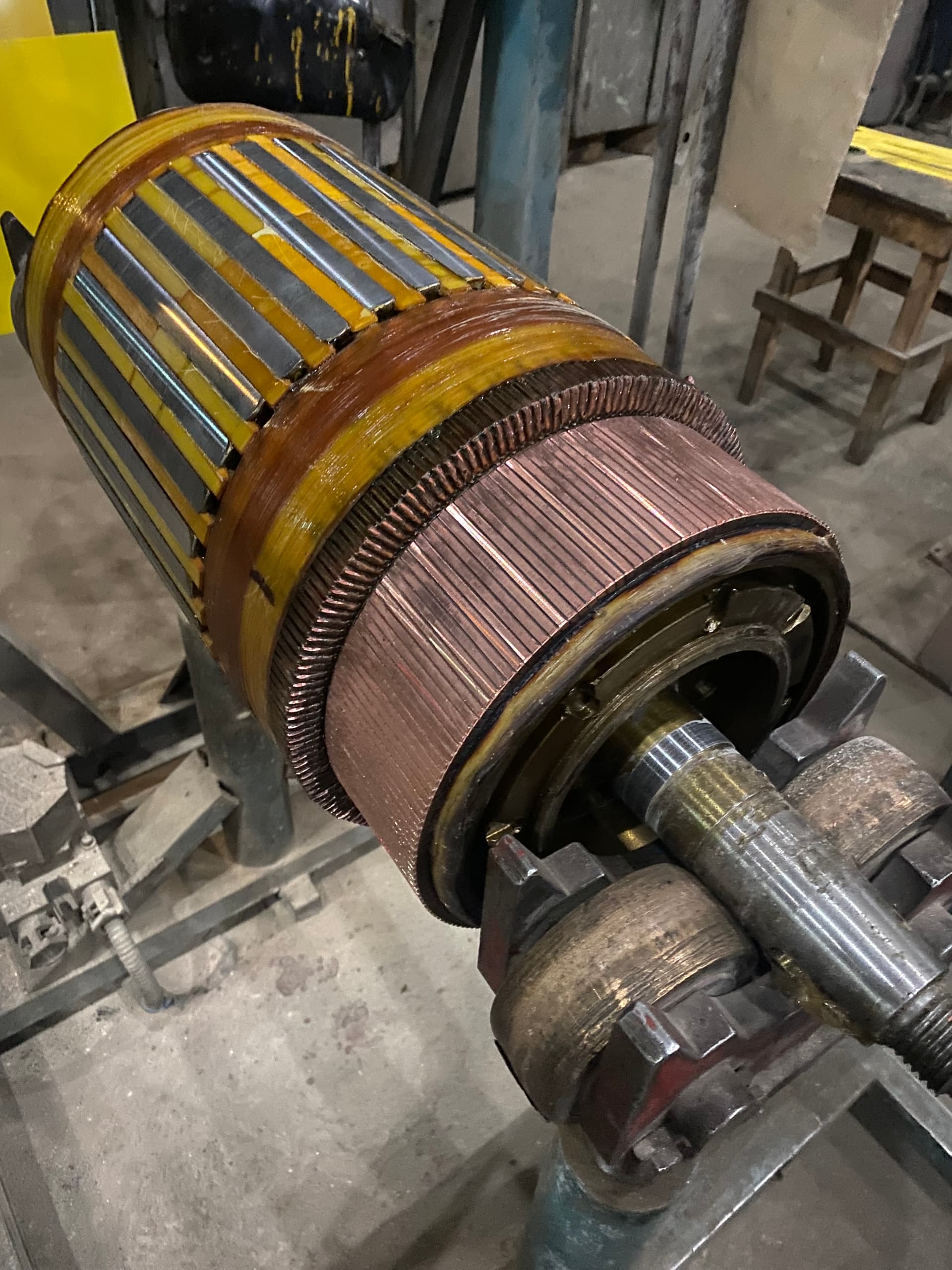
Traction motor repair: the process for traction-service conditions
  1. // ELEKTROPROMREMONT
  2. Traction motor repair

Traction motor repair: the process for traction-service conditions

The article “Traction motor: design, duty conditions and repair” covers the general picture — where traction motors are used, how they differ in construction from stationary DC machines, and what faults are typical for them. This article is the practical follow-up: a detailed technological route through the repair itself, focused on what needs to be done differently from repairing a general-purpose industrial DC motor.

At its core, repairing a traction motor is the same process described in “How DC motors are repaired”: fault detection, disassembly, electrical diagnostics of the armature and commutator, rewinding where needed, mechanical restoration, reassembly, balancing, testing. This article does not repeat the technique of armature rewinding, the surge test, commutator undercutting, or the other “base” operations — those are covered in depth in the DC motor repair process article.

What follows instead is what specifically needs extra attention on that route because of traction service: constant start-stop-reversal, vibration, dust and moisture, shock loads on the shaft and bearings, and a level of frame sealing that matters far more here than for a motor sitting in a clean workshop.

A technically sound traction motor repair should answer several practical questions:

  1. 01What, beyond the standard set of measurements, is worth finding out about the motor’s duty history before fault detection begins?
  2. 02Why does disassembling and reassembling a traction motor demand more attention to seals and protective covers than repairing a stationary machine?
  3. 03Why does armature and commutator work make up the bulk of a traction motor repair specifically?
  4. 04What testing confirms the motor will hold up under the real traction-service cycle, not just a no-load run?

Short answer

A traction motor repair goes through the same technological stages as a stationary DC motor repair — but the order of priorities and the weight given to individual stages shift to match traction-service conditions:

  1. 01Intake with fault detection that accounts for duty history, service type (transport, crane, mining equipment) and prior failures, not just the current condition.
  2. 02Disassembly with marking and documentation of every seal, labyrinth and protective cover before it comes off.
  3. 03Detailed electrical diagnostics of the armature, commutator and field winding — the same methods used for any DC motor, but read against the accelerated wear expected from traction duty.
  4. 04Armature winding repair or rewinding — the technique is covered in the DC motor repair process article; for a traction motor, the soldered joints to the commutator and the winding bandages are additionally checked for vibration fatigue.
  5. 05Commutator repair or manufacturing — accounting for the fact that a traction motor’s commutator wears and burns far faster than in a stationary machine of the same power.
  6. 06Pole-system repair — checking main and interpole coils for winding integrity and for how securely they are mechanically fixed, since vibration-induced loosening is specifically a traction-service pattern.
  7. 07Shaft repair or replacement — with extra attention to fatigue cracking from shock loads, not just run-out and worn fits.
  8. 08Bearing replacement with bearings rated for radial and shock loads, checking the housing fits for fretting corrosion caused by vibration.
  9. 09Restoring seals, labyrinths, cable entries and protective covers during reassembly.
  10. 10Dynamic armature balancing in the fully assembled state, to a tighter standard because of the continuous vibration the motor sees in service.
  11. 11Acceptance testing that, where practical, simulates the real start-stop-reverse cycle under load rather than stopping at a no-load check.

The exact scope depends on the type of traction motor (tram, locomotive, crane mechanism, mining machine), its power, and the actual condition found during fault detection.

Intake: fault detection that accounts for traction service

Standard fault detection — a visual inspection, insulation-resistance measurement, shaft run-out check, a look at the brush-commutator assembly — is done for a traction motor the same way it is for a stationary one. But for a traction motor it is incomplete without knowing the actual regime and environment the motor has been running in.

Duty history and operating conditions

Before disassembly, it is worth finding out from the operator:

  • the service type — electric transport, main-line locomotive, crane, quarry or mining equipment — since each type produces its own characteristic wear profile;
  • a rough count of starts, stops and reversals per shift or per route;
  • the operating environment — dust, moisture, quarry or ore dust, outdoor duty versus an enclosed depot;
  • the date and scope of any previous commutator, brush or bearing work;
  • whether sparking, overheating, unusual vibration or a burning smell were noticed before the motor was pulled;
  • whether the motor is fed from a thyristor or transistor converter, which affects the risk of bearing currents.

Without this information, fault detection only records the motor’s current condition without explaining how it got there — and without understanding the cause, the repair risks fixing the symptom while leaving the factor that will take the motor out of service again.

Wear patterns characteristic of traction service

During inspection, look for signs that point directly to a demanding start-stop-reverse duty and a contaminated environment:

  • uneven burning of the commutator’s running surface, often shifted toward the dominant direction of rotation;
  • shock-loading marks on the bearings — local raceway pitting rather than uniform wear;
  • darkened, brittle rubber seals and lip seals from heat, grease, or ozone from sparking;
  • carbon dust built up in the undercut grooves and in ventilation passages;
  • corrosion or moisture traces inside the frame with no visible external damage — a sign that sealing was lost well before the motor came in for repair.

Comparing the wear found on inspection against the known duty history is what separates normal traction-service wear from the aftermath of a single failure event — and lets the repair scope be adjusted accordingly.

Contamination by service type

The nature of the contamination depends heavily on where the motor was in service:

Traction service typeTypical environmental contaminationWhat to pay attention to during fault detection
Tram, trolleybus, metro trainroad and brake dust, higher moisture in wet weatherthe condition of undercarriage-side seals, brake dust contamination on the commutator
Main-line electric locomotiveballast dust, oil-laden vapor from auxiliary equipmentthe condition of the axle-box labyrinth seals, oil contamination of the winding
Quarry dump truck, excavator, draglinequarry and ore dust, moisture in pit workings, outdoor temperature swingsventilation passages clogged with dust, corrosion from moisture in the bearing housings
Overhead, gantry, portal craneshop-floor or outdoor site dust, grease and hydraulic fluidgrease reaching the commutator and brushes, the condition of seals on the hoist-mechanism side

This information shapes not only the diagnosis but the scope of seal and frame-protection work — covered below.

Disassembly: a compact, sealed construction calls for care

A traction motor is built more compactly and more tightly sealed than a stationary industrial motor of the same power — which demands more care specifically at the disassembly stage.

Marking and documenting the seals before disassembly

On top of the standard marking of the end shields’, rocker’s and poles’ relative positions, disassembling a traction motor also records:

  • the location and type of every sealing ring, lip seal and labyrinth groove at each joint;
  • the routing and fixing of cable entries and cable-gland seals;
  • the position of protective shields and covers relative to the vent openings;
  • the visible condition of every sealing element — hardening, cracks, deformation — so it is clear on the spot what needs replacing rather than refitting.

Removing the sealed assemblies

Disassembly follows an order that minimizes the risk of damaging the seals: the outer protective covers and shields come off first, then the cable entries with the wiring recorded, and only after that the end shields with their labyrinth seals.

Seals that have sagged, hardened, or seized from years of moisture and dust are easiest to damage with brute-force disassembly — so wherever possible, controlled heating or the correct pullers are used instead of a hammer.

Withdrawing the armature

The technique for withdrawing the armature from the frame — on a stand, keeping the core clear of the poles — is the same as described for DC motors generally. For a traction motor, it is worth remembering that the armature is often heavier than its frame size would suggest, because of the reinforced construction built for shock loads, so the lifting gear and slings need to be sized with that in mind rather than the machine’s nominal power.

Armature and commutator repair: the bulk of the work

Because commutation happens under a far harder duty — constant starting, reversal and load changes — a traction motor’s brush-commutator assembly and armature winding wear out much faster than in a stationary machine. That is why armature and commutator work makes up most of the scope in a traction motor overhaul.

The electrical diagnostic methods (megohmmetry, the surge test and growler check of sections, the ring-flux core test) and the technique for rewinding the winding and machining the commutator are the same ones covered in the DC motor repair process article, and are not repeated here. What follows is only what is specific to traction service.

How accelerated wear changes the scope of the repair

  • a traction motor’s commutator more often needs a full re-turn even at moderate burning, because the margin on diameter runs out faster from repeated skimming at earlier repairs;
  • the depth of mica undercutting is chosen with the knowledge that carbon dust and outside dirt build up in the grooves faster than in a clean shop;
  • the soldered or brazed joints between the coil leads and the commutator risers are checked for fatigue cracking from the combination of thermal cycling and vibration — a defect less typical of stationary machines;
  • a full commutator replacement is called for more often than partial bar replacement, since accumulated fatigue in the bar fixing under traction duty raises the risk of a repeat defect from a spot repair.

A crack in the soldered joint between a riser and a coil lead is not always visible from outside and does not always show up as an insulation-resistance deviation — it is found with a surge test or a close visual check under magnification, which is exactly why skipping that check is riskier on a traction motor than on a stationary one.

Armature winding: bandaging for a vibrating duty

The technique for laying the winding and bandaging is common to all DC motors. For a traction motor, bandage tension and the fixing of the end windings are checked to a stricter standard, since continuous vibration speeds up bandage loosening that would develop much more slowly in a stationary machine.

Pole system and compensating winding

Heavy-duty traction motors — locomotive traction motors, high-capacity crane motors — often carry a compensating winding in slots cut into the pole faces. It is checked and repaired on the same principles as the field winding, with attention to the slot fixing, which has to withstand the same vibration loading as the armature winding itself.

Pole system and mechanical repair for shock-load duty

Main and interpole coils

The main and interpole (commutating) coils are checked for resistance, interturn shorts, and insulation integrity — exactly as on any DC motor. The check that matters specifically for traction service is how securely the coils are mechanically fixed to the frame: vibration gradually loosens the mounting bolts, and a coil that has shifted or works loose on the pole core produces an unstable air gap and degrades commutation before the winding itself develops an electrical fault.

  • pole mounting bolts are checked against a torque spec and, where needed, secured with thread-locking compound;
  • the fit of each coil against its pole core is checked for play — none is acceptable, even with no visible winding damage;
  • pole polarity sequence is verified after any disassembly — a mistake here causes heavy sparking even with a perfectly sound armature.

Shaft

A traction motor’s shaft is checked for run-out, bending and worn fits the same way a stationary motor’s is, but with extra weight given to fatigue cracking — that, rather than gradual wear, is the typical cause of shaft failure under the shock loads coming from an uneven track or ground and from the gear drive.

  • zones with elevated fatigue risk — diameter transitions, the keyway, the gear-mounting fit — are checked with magnetic-particle or dye-penetrant inspection, not measurement alone;
  • a fatigue crack that is found is never covered with weld build-up — the cracked section is machined out down to sound metal, or the shaft is replaced outright;
  • worn fits are restored by metallizing, welding, or a repair sleeve only once the absence of cracks in that zone has been confirmed.

Welding or metallizing over an undetected fatigue crack does not fix the defect — it only hides it for a while. The crack keeps growing under the new layer and, more often than not, ends in a shaft failure out in service rather than in the shop.

Bearings

Bearings removed for a repair are, as a rule, replaced rather than refitted — that holds for a traction motor just as it does for a stationary one. What is specific to traction service is the choice of bearing type and the condition of the housing fits:

  • roller bearings are more often used in place of ball bearings of the same size to handle radial and shock loading;
  • the bearing housing fits are checked for fretting corrosion — fine metal loss from vibration-induced micro-movement that is not always obvious without a close inspection;
  • on motors fed from a frequency converter, the risk of bearing currents is assessed, and insulated bearings or a shaft grounding brush are fitted where needed.

The detailed bearing-checking methodology — temperature, noise, vibration, ultrasound, inspection after removal — is covered separately and is essentially the same for a traction motor and a stationary one; only the points that need extra attention for traction service are noted here.

Sealing and protection on reassembly

For a motor running in a clean machine hall, frame sealing is a secondary concern. For a traction motor mounted on the bogie of a locomotive, crane, or mining machine, right next to the track, the ground, or quarry dust, it is one of the most important steps in reassembly: any gap undoes an otherwise well-executed electrical repair.

Parts that get replaced, not refitted

  • rubber sealing rings and shaft lip seals — they lose their elasticity with heat and time regardless of how they look;
  • gaskets at the end-shield joints and the terminal box;
  • cable-entry seals and gland nuts;
  • grease or felt in the labyrinth grooves, where the design calls for it;
  • the fasteners holding protective shields and covers — including their own gaskets, not just the sheet metal itself.

Checking the seal quality after reassembly

After reassembly, both the electrical parameters and the physical tightness are checked:

  • the labyrinth clearance is kept within drawing tolerance — too tight causes rubbing and heating, too loose loses its protective function;
  • every fastener on the covers and shields is tightened to a controlled torque, not by feel;
  • where practical, the frame’s degree of protection is verified with a water spray or a dust-blast test that simulates service conditions.

Refitting an old seal “as found” instead of replacing it is the cheapest way to undo the rest of the repair — the first rain shower or cloud of quarry dust after the motor goes back into service will find its way to exactly the same place it did before.

Balancing and vibration control

A traction motor sits permanently in a vibrating environment — from the undercarriage, the gear drive, and an uneven track or ground. That makes it far more sensitive to residual armature imbalance than a stationary machine bolted to a rigid foundation in a calm duty.

Why the imbalance margin is smaller

A small residual imbalance that would give a stationary motor an acceptable vibration level stacks, in a traction motor, on top of the vibration already coming from the travel mechanism. The combined load on the bearings and the winding insulation grows non-linearly, so it makes sense to hold a traction motor to a tighter balancing grade than the bare minimum allowed for its power and speed.

Balancing practice

  • balancing is done in the fully assembled state — with the commutator, fan, key, and, where fitted, the coupling half or gear wheel in place;
  • the elongated armatures of locomotive traction motors are balanced in two planes, not one;
  • imbalance correction is done in the planes the design provides for, without drilling or welding on correction weights anywhere that would weaken the part;
  • results are recorded in a report showing the initial and residual imbalance for each plane.

Checking vibration on the assembled motor

Vibration is measured at the end-shield checkpoints across several conditions — no load, under load, and with reversal — and compared to the allowable levels for the chosen balancing grade. On the bench, unlike in service, there is no vibration coming from the gear drive or undercarriage, so the measured level reflects the armature and the assembly itself, with no outside sources mixed in.

Acceptance testing under traction-service conditions

The base test program — a no-load run, commutation checks, a load run, a high-voltage test — is the same one used for any repaired DC motor. For a traction motor, where the test bench allows, this program is extended with tests that simulate the real duty.

TestWhat it checks specifically for a traction motor
Starting under load (several times in a row)confirms stable commutation and no brush overheating in a regime close to a real move-off
Reversal under loadreveals a shifted neutral or commutation defects that do not show up running in one direction only
Intermittent duty (simulating start-stop cycling)reproduces the thermal and mechanical cycle typical of traction service, instead of one long steady run
Brief overloadchecks the margin on heating and commutation under forced duty — moving off on a grade, picking up a heavy load
Vibration checks across several duty pointsconfirms residual imbalance is not stacking on top of the vibration environment of real service
Sparking checks at every change of load and directioncaptures the state of commutation specifically during transients, not just steady running

Why a single no-load run is not enough

Some commutation defects, pole-coil fixing issues, and balancing problems only show up during transients — starting, reversal, or a sudden load change — not in steady no-load rotation. A motor that runs perfectly at no load can spark heavily on its very first reversal under load if, for example, the rocker is off the neutral by an angle too small to notice at steady state.

Comparing against the intake data

Acceptance test results are compared not only against standard limits but against the information gathered at intake — the expected number of starts and reversals per shift, the nature of the load, the operating environment. That makes it possible to judge whether the repaired motor will hold up under the actual duty it will run, rather than an abstract nameplate condition.

Common traction-service failure patterns and how a proper repair addresses them

The symptoms of a traction motor fault often match what shows up in a stationary machine — but the root cause, and therefore the correct repair scope, differs because of traction-service conditions.

01

Uneven commutator burning on one side

The symptom looks like local sparking or burning on part of the commutator. In a traction motor, the common cause is one direction of rotation or load dominating the real route, not a random fault in a single brush. A proper repair means a full re-turn of the commutator and equalizing pressure across all brush springs, not a spot cleanup of the burnt patch.

02

Sparking returns right after repair with a sound winding

If electrical diagnostics found no winding defect but sparking appears right after reassembly, the most likely cause is a rocker offset from neutral, or lost sealing that let dust or moisture reach the brush assembly before the first start. A proper repair verifies the rocker position with the millivoltmeter method or by minimum sparking rather than relying on the factory mark alone, and confirms the joints are sealed before start-up.

03

Bearings fail well ahead of their rated life

In a traction motor this is rarely simple time-related wear — more often the cause is shock loading, fretting corrosion in the housing fit, or bearing currents from the converter supply. A proper repair identifies the specific damage mechanism and restores the fit, selects the bearing type, or applies insulation accordingly, instead of just fitting a new bearing of the same type into the same fit.

04

A crack in the shaft near the gear-wheel fit or a diameter-transition fillet

This is a classic fatigue failure from gear-drive shock loading, not the result of a one-off overload. A proper repair calls for non-destructive testing of the entire shaft, not just the visibly damaged zone, and full replacement or cutting out the defective section — never weld build-up over the crack.

05

Loose fixing on the main or interpole coils

Vibration gradually loosens the mounting bolts even with no defect in the winding itself, eventually showing up as erratic sparking that is hard to trace to a specific cause. A proper repair checks the tightening torque on every fixing and applies thread-locking, rather than stopping at an electrical check of the coil.

06

Winding and commutator get contaminated again soon after repair

If a freshly repaired motor shows contamination and falling insulation resistance again within a few weeks of service, the cause is usually not the electrical repair itself but frame sealing that was never properly restored. A proper repair replaces the seals instead of refitting them, and confirms actual tightness after reassembly.

Frequently asked questions

How does repairing a traction motor differ from a regular repair?

The operations are the same as for a stationary DC motor, but fault detection accounts for duty history and operating conditions, more attention goes to the commutator and brush assembly because of accelerated wear, and reassembly always includes a full restoration of the seals and protective covers.

How often does a traction motor need to be repaired?

The interval between overhauls is tied to running hours or mileage rather than a calendar date, and is noticeably shorter than for a stationary industrial motor of the same power because of the harder commutation duty and the outdoor environment. The exact interval is set by the maintenance schedule for that motor type and the actual condition found at a scheduled inspection.

Can a traction motor be repaired without factory drawings?

Yes, provided the winding data, the connection scheme between the coils and the commutator, and the pole polarity are recorded before disassembly or reconstructed from markings on the machine itself. Without that record, restoration is still possible but needs extra diagnostic work — measuring the winding pitch, counting turns, and working out the connection scheme from a sound sample or from a similar machine.

Does the motor have to be fully disassembled just to repair the commutator?

No. Turning, undercutting and polishing the commutator without removing it from the armature can often be done without fully disassembling the motor — the extent of disassembly depends on the commutator’s condition and whether access to the armature winding is needed.

Why is simulating a start-stop-reverse cycle on the bench a required step after repair?

Some commutation, pole-coil fixing and balancing defects only show up during transients — not during steady no-load rotation. A test that simulates the real cycle catches these defects before the motor goes back into service.

What if the motor’s duty history is unknown, for example with a used motor bought secondhand?

In that case fault detection is broadened: the wear on the commutator, bearings and seals is examined more closely to reconstruct the operating conditions indirectly, and acceptance testing follows a more conservative program built around the worst plausible service scenario.

Can a bearing from a different manufacturer be fitted during a traction motor repair?

Yes, as long as the new bearing matches the type, fitting dimensions, and load class of the original — radial and shock capacity, and electrical insulation where the motor runs from a frequency converter. Choosing a bearing on outer dimensions alone, without matching the load type, raises the risk of premature failure.

EPR (Elektropromremont) services

Electropromremont LLC carries out capital repair of traction motors for electric transport, crane equipment and mining machinery, accounting for the wear patterns specific to traction duty — from the brush-commutator assembly through to the frame’s sealing.

The scope of work is set by the fault-detection results and can include:

  • fault detection on the armature, commutator, and brush-commutator assembly, accounting for duty history and operating conditions;
  • armature winding repair or rewinding;
  • commutator manufacturing, turning, undercutting and polishing;
  • pole-system repair — main and interpole coils, field windings and compensating winding;
  • shaft repair or replacement with non-destructive testing for fatigue cracks;
  • bearing replacement with bearings rated for shock and radial loads;
  • restoring seals, labyrinths, cable entries and protective covers;
  • dynamic armature balancing in the assembled state;
  • acceptance testing that simulates the real start-stop-reverse cycle.

Conclusion

Repairing a traction motor is the same technological process as repairing a stationary DC motor, adjusted for the conditions the machine actually runs in: frequent starts and reversals, continuous vibration, dust, moisture, and shock loads. These adjustments are not confined to one stage — they run through nearly the entire route, from fault detection to acceptance testing.

A motor that comes out of repair electrically flawless but fitted with worn-out seals, or tested without regard for its real duty, will be back in the shop well ahead of the service life it should have delivered — which is exactly why every nuance covered in this article affects the real service life, not the nameplate one.

Important disclaimer

This material is for informational purposes. The values, diagnostic methods, scope of work and recommendations given here are general and do not replace the manufacturer’s technical documentation. The final decision for a specific machine is made from its own diagnostics and inspection, taking into account its type, power, design, duty, operating history and applicable standards.

Need a repair for a traction motor?

We carry out fault detection that accounts for the operating conditions, armature, commutator and pole-system repair, shaft and bearing restoration, frame resealing, dynamic balancing, and acceptance testing that simulates the real start-stop-reverse cycle.

Get a consultation