Connecting coils to the commutator bars in the wrong order
Even a technically flawless winding will spark and overheat if its leads are connected to the bars out of the original sequence.
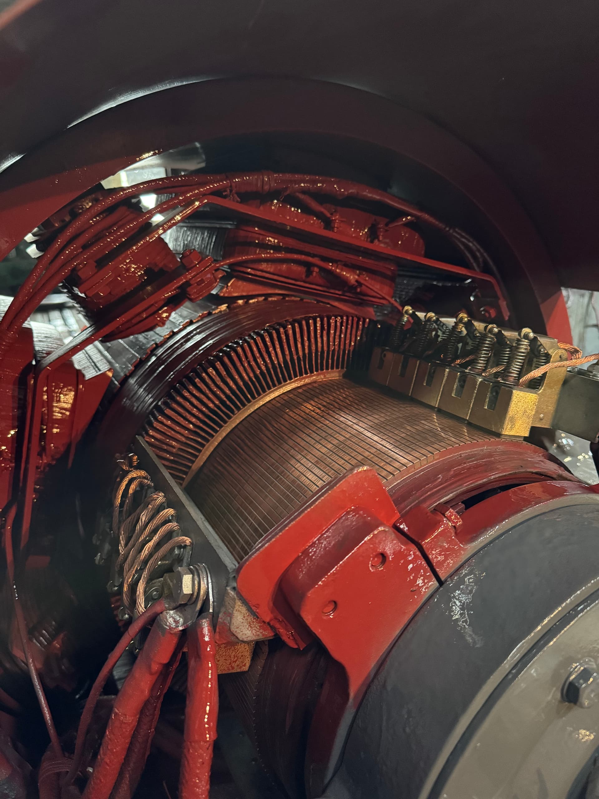
Repairing a DC motor looks, at first glance, like repairing an induction or synchronous motor: intake, fault detection, teardown, winding restoration, assembly, testing. But the construction of a DC machine is different, so the repair route differs from it in substance as well.
In an induction motor the main working winding is stationary and sits in the stator, while the rotor is most often a simple squirrel cage with no winding and no sliding contacts. A DC motor is the reverse: the field winding is stationary, carried on the main and commutating poles of the frame, while the working winding — the armature winding — rotates with the shaft and is connected to the commutator, against which the brushes slide. That is why the bulk of the complexity, cost and risk in a repair sits in the rotating part of the machine — the armature and the commutator.
A mistake made while rewinding an induction motor’s stator ruins that winding. A mistake in the order the armature coils are connected to the commutator bars ruins the commutation of the whole machine — the motor can come out of such a repair sparking, overheating, and failing again quickly, even though every individual part was made correctly. What follows is the complete technological process for repairing a DC motor, with the emphasis on the work that is specific to the armature and the commutator.
A proper DC motor repair has to answer several practical questions:
A typical DC motor repair includes:
The exact scope depends on the motor’s power, construction, the extent of the damage and its duty — for example, a traction, crane, or rolling-mill motor.
In induction or synchronous machines, almost all of the "winding" repair work concerns the stationary stator. A DC machine is the opposite — the winding that most often needs rewinding rotates with the shaft and is continuously switched by the brushes through the commutator.
| What we compare | Induction motor | DC motor |
|---|---|---|
| Stationary winding | Stator winding — usually the one that gets rewound | Field winding on the poles — fails less often, is not always rewound |
| Rotating part | Rotor — mostly a squirrel cage with no winding | Armature — has a winding and a commutator |
| Sliding contact | None (except in a wound rotor) | Mandatory: brushes against the commutator |
| Typical cause of a repeat failure after a poor repair | Phase imbalance, a core defect, loosened insulation | Coils connected to the wrong bars, a shifted neutral, an unfinished commutator |
That is why almost every "winding" stage of a DC motor repair is specific to it: checking, removing, manufacturing and laying the armature winding, working on the commutator, and setting the brush rocker. Repairing the field winding on the poles follows the same principles as repairing stator coils, so this article gives it less attention.
If the commutator and the armature winding are technically repaired correctly, but the coils are connected to the bars in the wrong order or the rocker is not set on the neutral, the motor will still spark and overheat.
On intake the nameplate data and accompanying information are recorded:
If the nameplate is damaged or missing, winding data are recovered from the datasheet, the drawing, earlier repair reports, or the markings on the armature or pole windings themselves.
Because the armature and the commutator are especially sensitive to overload, load swings and incorrect supply, the customer is asked:
Without this information, even careful armature and commutator fault detection may not reveal why the failure happened, and the repair risks repeating the same fault.
Before teardown, a set of checks is carried out that gives an initial picture of the armature, commutator and field winding condition.
A megohmmeter is used to measure the insulation resistance of the armature winding against the frame (via the brushes or directly at the commutator) and of the field winding against the frame and against the armature. Measurements are taken both before and after cleaning, since a dirty commutator often understates the reading.
An acceptable insulation resistance does not rule out an interturn short in an armature coil — that defect is found by separate methods during the detailed diagnostics stage.
Brush spring force, the free movement of brushes in their holders and the condition of the flexible leads are checked separately, along with commutator run-out and ovality using a dial indicator while the shaft is turned slowly.
The results of the initial fault detection determine whether the repair can be limited to the commutator and the bearings, or whether a full teardown with detailed electrical diagnostics of the armature winding is required.
Before teardown, the relative positions of the end shields, the rocker, the poles and the field-winding leads are marked — reinstalling the rocker in the correct position relative to the neutral is critical for commutation.
The armature is pulled out of the frame bore on a dedicated rig, or with guides and lifting gear, so the armature core never touches the poles or the field winding.
Contact between the armature core and a pole shoe, even at low withdrawal speed, can damage the armature teeth and the stator’s field winding.
The commutator is taken off the armature only when necessary — for a full commutator replacement, an internal-joint repair, or access to the slots underneath it. Removal is accompanied by recording the connection scheme between the coils and the bars.
Bearings are removed with the force applied to the ring that has the interference fit, using pullers or controlled induction heating. At the same time, the seals, labyrinths and grease chambers are checked.
After teardown, an in-depth check of the armature, commutator and field winding uncovers defects that the initial inspection could not.
The insulation resistance of the armature winding and of every field winding — separately excited, shunt, series, commutating-pole, compensating — is measured against the frame separately.
The armature coils are checked for an interturn short with an impulse surge tester or on an induction-type growler. Both methods find shorted or damaged turns that a plain insulation-resistance reading cannot.
Skipping the surge test or the growler check is one of the most common reasons a rewound armature fails again after only a few hours of running.
The armature core is checked for interlaminar shorts with a ring-flux loop test or thermal imaging — local overheating of the stack points to shorted laminations, which have to be fixed before the new winding is laid in.
The main pole coils (the field winding) and the commutating-pole coils are checked for resistance, an interturn short, and continuity. Pole polarity sequence is checked separately — it must match the factory scheme, or reassembly can mix up the N-S-N-S sequence, which causes heavy sparking even in a sound armature.
On motors with series, shunt, or compound excitation, the continuity and resistance of the series winding (high-current, few turns of heavy wire) and the shunt winding (many turns of fine wire) are checked separately, along with their insulation against the frame and against each other.
The results of every check are logged in the incoming electrical diagnostics report, which becomes the baseline for comparison with the final test results.
If diagnostics confirm an interturn short, an open circuit, a ground fault, or mechanical damage in the armature winding, the old winding is removed.
Before the winding is removed, the following are recorded:
A mistake in the winding pitch or in the connection order to the commutator changes the commutation characteristics even when the number of turns and the wire gauge are reproduced correctly.
The old winding is removed by controlled burn-out in an oven, mechanically, or by a combination of both, without damaging the teeth or the interlaminar insulation of the core. Once removed, the slots are cleaned and the core is checked again.
The main or commutating pole coils are taken off the frame only once damage — an open circuit, an interturn short, or an insulation breakdown — is confirmed. Before removal, the number of turns, wire gauge and polarity of each coil are recorded.
New armature coils are wound to the recorded winding data — the same pitch, turn count, wire gauge and grade. Coils are wound on formers that reproduce the slot shape and end-turn geometry of the original.
Depending on its condition, the commutator is:
A new commutator is built to the exact original pitch and bar count — that number always matches the number of armature coils.
New main pole, commutating pole, or compensating winding coils are made to the original turn count, wire gauge and connection scheme when needed, keeping strictly to the polarity sequence.
Laying the new armature winding is the most demanding stage of the repair, because it decides whether the machine will commutate correctly.
Every coil lead is connected to a specific, predetermined commutator bar, following the scheme that matches the winding’s commutator pitch. The joint is made by soldering or welding, giving a low contact resistance and mechanical strength.
Connecting the leads to the bars in the wrong order is a common reason a rebuilt armature sparks harder after the repair than it did before, even though every coil on its own is sound. This mistake cannot be caught by inspection — only by a surge test or a trial run with sparking monitored.
The winding’s end turns are secured with fiberglass tape or wire banding at the tension called for in the drawing — too little tension lets the winding shift under centrifugal force, too much damages the wire insulation.
After laying and banding, an interim electrical check follows: insulation resistance, winding resistance, and the symmetry of resistance between neighboring commutator bars.
The new armature winding is impregnated with varnish or resin to raise its dielectric strength, its mechanical resistance to centrifugal force, and its protection against moisture and contamination.
After impregnation the armature is baked in an oven on a cycle matched to the varnish or resin, with temperature, dwell time, and insulation resistance monitored throughout the bake.
Incomplete curing leaves the armature winding sensitive to moisture and vibration even after a formally completed impregnation cycle.
Unlike the stator’s stationary winding, a rotating armature is under constant centrifugal load, which is why impregnation quality here is especially critical for the long-term integrity of the banding and end turns.
The shaft is checked for run-out, bending, cracks and worn seating surfaces. Depending on the defect, it is straightened, built up by welding or metallized at the seats, fitted with a repair sleeve, or replaced outright.
Bearings removed to gain access for armature fault detection are, as a rule, replaced with new ones — reusing a bearing that has been pulled off an interference fit, or that shows even minor wear on its raceways, raises the risk of an early failure.
Refitting old bearings to save on parts is a common shortcut that saves little on materials but cuts the motor’s service interval many times over.
Worn bearing seats on the shaft and in the end shields are restored by metallizing, thermal spraying, weld buildup, or a repair sleeve, followed by machining to the required diameter, roundness and finish.
The frame is checked for cracks, deformed feet, and the condition of the pole and end-shield seats; welding, machining of the mounting surfaces, and re-cutting threads are carried out as needed.
Once the armature winding is laid, impregnated and the commutator fitted, its final machining takes place.
The commutator is turned to its final diameter on a lathe or a dedicated commutator lathe, removing the minimum stock needed to clear run-out, ovality, and traces of earlier wear or sparking.
The inter-bar insulation (mica) is recessed below the copper to the correct depth — too shallow and the mica stays proud and breaks brush contact, too deep and carbon dust builds up faster in the grooves.
The running surface is polished to the required finish, bar edges are chamfered, and copper burrs left over from undercutting are removed.
Commutator geometry — run-out, ovality, roughness — is checked after every operation, not just at the end, because a mistake made while turning cannot be corrected by polishing alone.
The armature is fitted into the frame with the same care used to remove it — no contact between the core and the pole shoes, and no impact loads on the commutator.
The position of the rocker, and with it the brushes, relative to the geometric and magnetic neutral is one of the most important assembly parameters. The rocker is set to the factory marking, or located by the induced-voltage (millivoltmeter) method, or by finding the point of minimum sparking during a trial run.
A rocker off the neutral degrades commutation just as badly as a defect in the armature winding itself — which is exactly why its position is always marked before teardown.
Spring force is equalized across every brush of a given polarity and checked with a gauge, not by hand. Too little force lets a brush bounce and spark; too much accelerates wear on both the brush and the commutator.
New brushes are bedded to the commutator profile with glass paper of the right grit — never sandpaper with a metallic or silicon abrasive — until the contact face shows an even imprint along its whole length.
Balancing the armature is mandatory after rewinding, replacing the commutator, repairing or replacing the fan, straightening the shaft, or any other work that changes the mass distribution of the rotating part.
Balancing an armature without its commutator or banding fitted gives a misleading result — the final assembly needs to be checked for balance again.
The assembled motor goes through a set of acceptance tests that confirm the quality of the armature, commutator and related work.
The motor is started unloaded, checking smooth acceleration, direction of rotation, noise and vibration levels, bearing temperature, and field current symmetry.
Brush sparking is assessed first unloaded, then under load — light, even sparking with no blue or white flashes counts as normal; any increase in sparking as load or speed changes points to an uncorrected commutation defect.
The motor is loaded to its rated value and, where the test program calls for it, up to overload, while armature and field current, speed, winding heating and commutator temperature are monitored.
The armature and field winding insulation is tested with an elevated power-frequency voltage against the frame — this confirms the dielectric strength of the insulation restored during the repair.
Vibration is measured at reference points on the end shields, both unloaded and under load, and compared against the limits for the motor’s balance quality grade.
Test protocols are produced from every result and attached to the motor’s accompanying documentation.
How long a DC motor repair takes depends chiefly on the amount of work needed on the armature and commutator, not just on the motor’s power.
| Scope of work | Typical timeframe | What drives the complexity |
|---|---|---|
| Commutator and brush repair, no rewinding | 2–5 working days | Availability of spare brushes, depth of turning needed |
| Bearing replacement and mechanical repair | 3–7 working days | Condition of the seats, whether the shaft needs restoring |
| Partial rewinding of the armature | 7–14 working days | Number of damaged coils, availability of the correct wire grade |
| Full armature rewind with a new commutator | 14–25 working days | Armature size, whether a new commutator must be built, balancing |
| Capital repair including pole and compensating-winding work | 20–35 working days | Frame condition, scope of field-winding repair, the test program |
These timeframes are indicative and are refined after fault detection — building a non-standard commutator or sourcing an unusual wire grade can extend a repair considerably.
Even a technically flawless winding will spark and overheat if its leads are connected to the bars out of the original sequence.
An interturn short in a single coil does not always show up in the insulation resistance reading — without an impulse test it goes unnoticed until the next failure.
A bearing pulled off an interference fit has a shortened service life and a higher risk of failure even with no visible damage.
Contact over only a small part of the brush face raises current density there, causing local heating and rapid sparking right after the repair.
A broken polarity sequence degrades commutation badly enough to cause sparking even in a sound, correctly rewound armature.
Mass distribution changes once the commutator and banding are fitted, so balancing without them does not reflect the true imbalance of the finished armature.
An incompletely cured varnish leaves the winding vulnerable to moisture and vibration even though the impregnation cycle was formally completed.
Without checking the neutral, the rocker can be off by an angle too small to notice visually but large enough to cause heavy sparking under load.
Some commutation, field-winding and balancing defects only show up under load, so a no-load test alone cannot confirm the quality of the repair.
No. If diagnostics — megger testing, a surge test, visual inspection — find no interturn short, open circuit or ground fault, the repair can be limited to the commutator, the bearings, and other mechanical work.
Anywhere from a few days for commutator and brush work to three to five weeks for a full armature rewind with a new commutator — the exact time depends on the extent of the damage and the availability of materials.
In most cases yes — turning, undercutting, polishing and replacing individual bars restore the running surface without a full replacement. A full replacement is only needed for significant wear, cracked insulating cones, or failed bar retention.
The connection order sets the winding’s commutator pitch. A mistake shifts the commutation phase relative to the neutral and causes heavy sparking even in a fully sound winding.
A preliminary balance of individual parts is possible, but the final balance is always done fully assembled — with the commutator, the fan and the banding in place.
Only if the new grade matches the machine’s electrical characteristics — resistivity, allowable current density, and its ability to support commutation. A grade that merely fits the physical size can cause heavy sparking.
The most common causes are coils connected to the commutator in the wrong order, a shifted brush rocker, brushes that were not bedded in, or mixed-up commutating-pole polarity after reassembly.
EPR (Elektropromremont) carries out the full cycle of DC motor repair in-house — from armature and commutator fault detection to manufacturing new coils, commutators and pole windings, balancing, and acceptance testing.
The scope of work includes:
This material is for informational purposes. The values, diagnostic methods, scope of work and recommendations given here are general and do not replace the manufacturer’s technical documentation. The final decision for a specific machine is made from its own diagnostics and inspection, taking into account its type, power, design, duty, operating history and applicable standards.
We carry out full fault detection on the armature, commutator and field winding, determine the required scope of repair, and perform the complete cycle of work — from rewinding to balancing and acceptance testing.