What is the difference between static and dynamic balancing?
Static balancing corrects mainly a single mass imbalance, while dynamic balancing accounts for mass distribution along the rotor’s length in two planes.
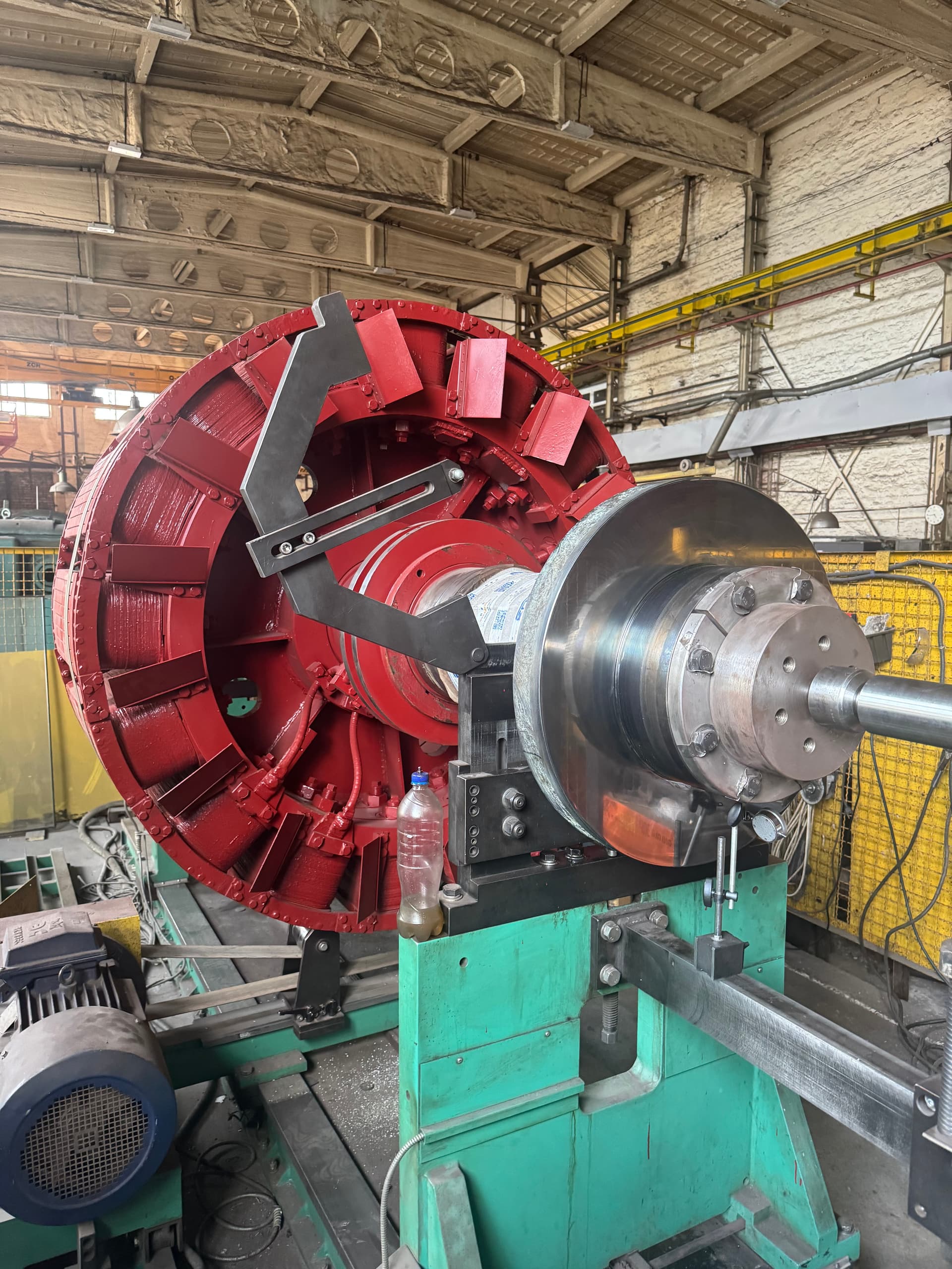
Rotor balancing is the process of finding and reducing the imbalance of a rotating part by correcting its mass distribution about the axis of rotation. In simple terms, balancing keeps the rotor from generating excessive centrifugal force and heavy vibration as it turns.
Balancing quality directly affects vibration levels, bearing life, noise, air-gap stability, coupling condition, foundation condition and the motor’s service life. Imbalance is a state in which the rotor’s mass distribution is not symmetric about the axis of rotation, so the center of mass does not coincide with the axis, and rotation produces a periodic centrifugal force.
That force grows with the square of angular velocity — double the speed and the centrifugal force roughly quadruples. That is why a small imbalance, barely noticeable at low speed, can become critical at high speed.
The causes fall into a few groups.
Even a new rotor can have imbalance, since a perfectly even mass distribution is practically unattainable in manufacturing — that is why rotors in critical machines are balanced during production. What remains after balancing is called residual imbalance, and it should stay below the allowable level for that rotor.
With static imbalance, the center of mass is offset from the axis of rotation — if such a rotor is placed freely on very light rests, its heavy side will tend to sink. Static balancing is used mainly for narrow parts where axial length is small relative to diameter — fans, pulleys, thin disks.
In a long rotor, the overall center of mass can lie on the axis while two unbalanced masses at opposite ends, 180° apart, still create a moment — the rotor starts to "rock" as it turns. That is moment imbalance, which is why most motor rotors need dynamic balancing: performed while the rotor spins on a dedicated balancing machine, correcting mass distribution in two planes.
In practice, most rotors have both a static and a moment component at once — this is called combined, or dynamic, imbalance.
The rotor is mounted on the machine’s supports; as it turns, sensors measure vibration, force, phase and speed. The system determines how much correction is needed, in which plane, and at what angle. Phase reveals the angular position of the unbalanced mass relative to a reference mark — without a phase signal, you can know imbalance exists but struggle to pinpoint where correction is needed.
Balancing often uses a trial weight of known mass placed at a specific position so the system can determine the rotor’s sensitivity, after which the software calculates the correction needed. Knowing the correction radius precisely matters — the same mass at a different radius creates a different imbalance, since imbalance is tied to the product of mass and radius.
The main methods are removing material (drilling, milling, grinding), adding mass (balance weights, screws, plates), or moving existing weights on designs with special adjustable elements.
Correction can only be made in technologically approved zones — drilling at random can weaken a part, damage the core or winding, or disrupt ventilation. Balance weights must be securely fastened: at high speed they too carry a large centrifugal force, and one coming loose can destroy the motor or wreck the bearings.
Balancing is done after a repair is finished, not before — any intervention (a new winding, a weld, weld overlay, machining) changes mass distribution, so balancing performed beforehand would be pointless.
A rigid rotor does not change shape significantly from elastic deformation within its operating speed range, so a balance achieved on a machine at low speed stays valid in service. A flexible rotor — typical of long shafts and high-speed assemblies — can deform significantly while spinning, pass through critical speeds, and change its mode shape, so it may need specialized high-speed balancing with several correction planes.
Critical speed is the range where the excitation frequency approaches the rotor system’s natural frequency; in that zone, vibration can rise sharply and the rotor can deflect heavily.
On a balancing machine, the rotor is removed and balanced separately. Field balancing is done without disassembly, as part of the assembled unit, when the rotor is large, disassembly is impractical, or the imbalance appeared only after installation — vibration of the assembly is measured and trial weights are fitted right at the installation site.
Field balancing must never be used to mask a bearing defect, a bent shaft, mechanical looseness, a crack, misalignment, or resonance — first confirm that imbalance is genuinely the cause of the vibration.
An induction motor rotor’s balance is checked after cage repair, bar or end-ring replacement, or fan or shaft work. Balancing a wound rotor matters especially after rewinding — the new winding, bands, wedges and impregnating material can shift the mass of different zones slightly.
Balancing a DC machine armature covers the shaft, core, winding, commutator, bands and fan as a complete assembly — even if a new commutator has the same nominal mass, the distribution of copper, solder joints and the fit can differ, so the assembled unit needs balancing, not just the commutator alone.
Imbalance places a cyclic radial load on the bearings, speeding up raceway fatigue, wear, heating and grease breakdown — so correct balancing directly affects bearing life. Heavy rotor vibration can also change the actual air gap during rotation, and in severe cases cause the rotor to touch the stator.
In DC machines, armature vibration can worsen brush-to-commutator contact, causing brush bounce, sparking, uneven wear and damage to the working film — so good armature balancing directly affects commutation.
After correction, the rotor is run again on the balancing machine, and residual imbalance, phase and reading stability are determined — the actual result can differ from the calculated one due to inaccuracies in mass, angle or radius, so balancing is nearly always an iterative process.
Different rotor types call for different accuracy grades — there is no point balancing a large low-speed rotor to the same requirements as a high-speed spindle. Overly strict requirements can raise cost substantially without a real benefit to the machine; the goal is a residual imbalance low enough for safe, stable operation.
| Sign | Possible cause | What to check |
|---|---|---|
| Vibration rises with speed | Imbalance | Rotor balance |
| 1× RPM dominates | Likely imbalance | Phase and spectrum |
| Vibration remains after balancing | Another defect | Shaft, bearings, alignment |
| Balance keeps changing | An unstable assembly | Core, weights |
| Vibration after rewinding or a fan change | A mass change | Dynamic balancing of the assembled unit |
| Vibration only after warm-up | Thermal distortion | Shaft, rotor |
| Strong axial vibration | Possible misalignment | Coupling, alignment |
| Vibration at a specific speed | Resonance | Critical frequencies |
| Bearings fail repeatedly | Imbalance or another dynamic issue | Vibration and geometry |
Static balancing corrects mainly a single mass imbalance, while dynamic balancing accounts for mass distribution along the rotor’s length in two planes.
Yes, if residual imbalance exceeds the allowable level or the repair changed mass distribution — for example, after rewinding the rotor, replacing the fan, or cage repair.
No, since the stator does not rotate and rewinding it does not change the rotor’s mass distribution.
No. The geometric defect or misalignment must be resolved or assessed first, and only then should the rotor be balanced.
Because the source can be a bearing, a shaft, a coupling, the foundation, resonance, or an electromagnetic defect rather than imbalance.
Practically, some allowable residual imbalance always remains.
Yes, field balancing exists, but it must not mask another defect — first confirm that imbalance is actually the cause.
EPR (Elektropromremont) diagnoses and dynamically balances rotating assemblies of electric machines after repair and restoration.
Depending on the design, rotors of induction and synchronous motors, wound rotors, DC machine armatures, traction rotors, fans and other rotating assemblies can be balanced.
Before balancing, the following may be performed:
This material is for informational purposes. The values, diagnostic methods, scope of work and recommendations given here are general and do not replace the manufacturer’s technical documentation. The final decision for a specific machine is made from its own diagnostics and inspection, taking into account its type, power, design, duty, operating history and applicable standards.
We carry out inspection, two-plane dynamic balancing, and verification testing of the rotor, with a full test report.