Is run-out the same as shaft bend?
Not always. The reading can include eccentricity, ovality, surface defects and datum errors.
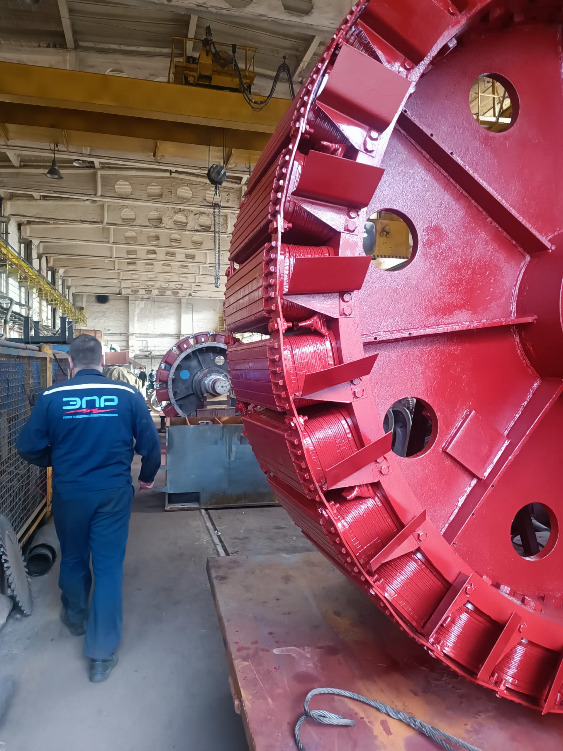
Shaft run-out is one of the most important geometric parameters of a motor rotor. It governs rotation stability, vibration levels, bearing condition, seal performance, alignment accuracy, and how uniform the air gap stays between rotor and stator.
Measuring run-out looks simple: turn the shaft and watch the indicator track the surface. Yet a wrong result can easily come from a dirty measuring surface, scoring or corrosion, a poorly mounted indicator, bearing play, deflecting supports, or errors in the centers or vee-blocks used.
A professional check therefore has to do more than record the indicator’s maximum swing — it has to establish which surface is being checked, what datum it was measured against, whether a bent shaft axis is the cause, and whether bearings, vee-blocks or center holes are influencing the reading.
Run-out is the change in position of a monitored surface relative to a given axis over one full revolution. In electric-machine repair, technicians check radial run-out, axial (face) run-out, the coaxiality of fitted surfaces, shaft straightness, eccentricity, ovality, and the run-out of a mounted coupling half, a commutator, slip rings, a fan, or the rotor core.
Total indicated run-out (TIR) is the difference between the indicator’s maximum and minimum readings over one full turn. An indicator reading does not always equal the actual bend in the shaft’s axis — it describes the movement of a specific surface relative to the chosen datum.
Common causes include a mechanical impact, a dropped rotor, improper transport, the motor jamming, the rotor touching the stator, a bearing failure, overload, incorrectly removing or fitting a coupling half, local overheating, thermal distortion, incorrect welding or weld overlay, a shaft crack, and sag in a long rotor under its own weight.
The need for a check may be signaled by high vibration at running speed, unstable balancing results, one or both bearings running hot, bearings failing quickly, coupling run-out, seal leakage, an uneven air gap, or shaft-end wobble visible to the eye.
Testing may call for a dial indicator (0.01–0.001 mm graduation), a digital or lever-type indicator, a magnetic stand, vee-blocks, roller rests, lathe centers, a balancing machine, a micrometer, an inside micrometer, a laser measuring instrument, and eddy-current displacement probes.
Before measuring, clean the shaft of grease and dust and inspect it for corrosion and mechanical damage. An indicator riding over a scratch, a burr or a pit will register a local irregularity, not the axis’s true geometric run-out — so never grind the surface freely before measuring, since that can erase important evidence of a defect.
The result always depends on the datum the shaft turns against — centers, vee-blocks, roller rests, or the machine’s own bearings. The right datum has to match the purpose of the check: to verify a coupling seat’s coaxiality with the bearing journals, reference the bearing fits; to assess overall shaft straightness, centers are typically used; to assess how the assembled rotor actually behaves, measure it in its own bearings or on a balancing machine.
Measuring on centers is convenient for checking straightness and journal coaxiality, but depends on the condition of the center holes, and a long rotor can sag under its own weight. Measuring on vee-blocks is simple and accessible, but sensitive to ovality of the base journals and to contamination. Measuring in the motor’s own bearings shows how the assembled machine actually behaves, but the result can include the bearings’ internal clearance and does not always distinguish shaft bend from a bearing-assembly defect.
Mount the indicator on a rigid base, as close as possible to the measuring point, with the plunger perpendicular to the surface and enough preload applied. A plunger set at a significant angle to the direction of travel introduces cosine error. For radial measurements, aim the plunger at the shaft axis; for face measurements, keep it roughly parallel to the axis.
Turn the shaft slowly, without jerks, in one direction, without pressing on it radially or creating axial movement. Avoid turning the shaft by pushing right next to the measuring point — hand pressure can elastically shift a long shaft or a rotor within its bearing clearance.
A single result cannot reveal the shape of a deformation. It is best to measure at both bearing journals, next to them, near the edges of the core, at the rotor’s middle, and at the coupling and fan seats. Changes in amplitude and phase along the shaft reveal the point of maximum bend, a local deformation, the eccentricity of a single fit, or misalignment between surfaces.
The 0° mark on the shaft end must stay the same at every cross-section — this lets you compare the phase of run-out along the whole shaft. If the maximum falls at roughly the same angular position at every section, that points to an overall bend; if the maximum jumps sharply in angle between neighboring surfaces, misalignment or a local machining error is more likely.
Axial run-out is measured on a face surface, with the indicator plunger set roughly parallel to the shaft axis. It can result from the face not being perpendicular to the axis, a distorted shoulder, contamination, a burr, or rotor end-float. It is especially important to check the face run-out of bearing-fit shoulders, coupling-half faces, flanges, slip rings and commutators.
If the rotor has axial play, it can drift back and forth during a face measurement — to stabilize it, apply a small, steady axial force in one direction, or use the machine’s own thrust arrangement, without reversing the direction of rotation.
A long or heavy rotor can sag elastically under its own weight, so a horizontal measurement can include both the actual residual bend and elastic sag from weight and support deflection. For accurate measurements of large rotors, engineers use sag calculations, additional steady rests, special roller supports, or measurement on a balancing machine — a steady rest must never mask the actual bend or force additional straightening.
Run-out describes a geometric deviation of a surface or axis and is measured while slowly turning the shaft by hand. Imbalance describes an uneven mass distribution about the axis of rotation and shows up dynamically — it is found on a balancing machine or through vibration. All combinations are possible: a shaft with run-out but a statically balanced rotor; a rotor with imbalance and little geometric run-out; or both defects present at once.
Balancing corrects mass distribution, not the axis geometry — significant run-out cannot be fixed simply by adding balance weights.
There is no universal allowable value for every electric motor — the tolerance depends on shaft diameter and length, rotational speed, motor power, bearing type, coupling design, seal type, air gap, and the manufacturer’s requirements. The main sources of criteria should be the shaft drawing, repair documentation, the manufacturer’s specifications, and the standards for that machine type — never rely on one arbitrary figure for every motor.
Repair may be needed if run-out exceeds the specified tolerance, a bend is confirmed, fits are misaligned, the coupling shows excessive run-out caused by the shaft, the air gap becomes uneven, or bearings keep failing. Depending on the design and the defect, mechanical or thermomechanical straightening, grinding, restoring a fit, fitting a repair sleeve, metal spraying, weld overlay, or manufacturing a new shaft may be used.
Straightening is a demanding operation: the wrong force can crack the shaft, damage a fit, or cause it to bend again. Before straightening, map the run-out, locate the plane of the bend, and check the shaft for cracks. When run-out is large or appeared suddenly, a crack must be ruled out with magnetic-particle, dye-penetrant, ultrasonic, or eddy-current testing — especially at fillets, keyways, threads and weld-overlay zones. Straightening a shaft with an undetected crack is dangerous.
Not always. The reading can include eccentricity, ovality, surface defects and datum errors.
No. Run-out needs a dial indicator, a non-contact probe, or a dedicated measuring system; a caliper or micrometer only helps determine ovality and taper.
No. Balancing corrects mass distribution, not shaft geometry.
It depends on the condition of the centers and the base journals. With sound center holes, mounting on centers usually gives a cleaner reference axis.
Possible causes include a contaminated fit, a burr, the wrong key, eccentricity in the coupling bore, or misalignment during mounting.
Yes. Uneven heating can cause a temporary thermal bend in the rotor.
The tolerance depends on the design, speed, diameter, bearings, coupling, and the manufacturer’s documentation. There is no single value for every motor.
EPR (Elektropromremont) performs comprehensive inspection, repair and testing of shafts and rotors in industrial electric machines.
The scope of work includes:
This material is for informational purposes. The values, diagnostic methods, scope of work and recommendations given here are general and do not replace the manufacturer’s technical documentation. The final decision for a specific machine is made from its own diagnostics and inspection, taking into account its type, power, design, duty, operating history and applicable standards.
We measure radial and axial run-out, build a map along the shaft, identify the cause of the defect, and carry out the repair needed.