Testing the rotor of an electric motor
  1. // ELEKTROPROMREMONT
  2. Rotor testing

Testing the rotor of an electric motor

Testing the rotor is one of the most important stages of electric motor diagnostics. Rotor defects can cause a loss of power, a longer acceleration time, torque pulsations, overheating, noise, vibration and uneven current consumption.

At the same time, rotor faults are often difficult to distinguish from:

  • a stator defect;
  • supply voltage unbalance;
  • overload;
  • a bearing fault;
  • incorrect alignment;
  • a problem with the driven mechanism;
  • incorrect variable frequency drive settings.

For example, broken bars in a squirrel-cage rotor may not immediately trip the protection. The motor keeps running, but it:

  • takes longer to accelerate;
  • starts worse under load;
  • loses torque;
  • runs with pulsations;
  • heats up more;
  • produces a characteristic hum;
  • gradually destroys the neighbouring bars and end rings.

A complete rotor check must include mechanical, electrical and magnetic diagnostics. The scope of the check depends on the design of the electrical machine.

Testing methods differ for:

  • the squirrel-cage rotor of an asynchronous motor;
  • the wound rotor;
  • the armature of a DC motor;
  • the rotor of a synchronous machine;
  • a permanent-magnet rotor.

The short answer

To test the rotor of an electric motor, it is necessary to:

  1. 01Gather information on how the motor was running before it was shut down.
  2. 02Analyse the start-up, the currents, the speed, the noise and the vibration.
  3. 03Check the shaft, the bearing seats and the mechanical runout.
  4. 04Inspect the rotor surface for traces of contact with the stator.
  5. 05Check the condition of the active-steel core.
  6. 06Inspect the fan, the balancing weights and the fastenings.
  7. 07Check the squirrel-cage bars and the end rings.
  8. 08Carry out testing of the rotor cage using special methods.
  9. 09Check the rotor for imbalance.
  10. 10For a wound rotor — measure the winding and insulation resistances.
  11. 11For an armature — check the winding, the commutator and the interturn insulation.
  12. 12For a synchronous rotor — check the field winding, the poles and the damper winding.
  13. 13Compare the results with the nameplate, repair and archived data.
  14. 14Carry out a verification test of the motor after reassembly.

There is no single universal instrument that can fully confirm the soundness of a rotor. A reliable conclusion is formed from the results of several complementary checks.

What types of rotors exist

Squirrel-cage rotor

Used in most asynchronous electric motors.

Main elements:

  • the shaft;
  • the active-steel core;
  • the cage bars;
  • the end rings;
  • the ventilation ducts;
  • the fan;
  • the balancing elements.

The bars and rings can be:

  • aluminium;
  • copper;
  • cast together;
  • fabricated and joined by brazing or welding.

Wound rotor

Has a three-phase winding, usually star-connected, brought out to slip rings.

It consists of:

  • the shaft;
  • the core;
  • the winding;
  • the slot insulation;
  • the end windings;
  • the bandages;
  • the slip rings;
  • the leads;
  • the balancing elements.

Armature of a DC machine

Main elements:

  • the shaft;
  • the steel core;
  • the armature winding;
  • the commutator;
  • the commutator risers;
  • the bandages;
  • the balancing weights;
  • the fan.

Testing this type of rotor largely comes down to diagnosing the armature winding and the commutator.

Rotor of a synchronous machine

May have:

  • a salient-pole design;
  • a non-salient-pole design;
  • a field winding;
  • a damper winding;
  • slip rings;
  • a brushless exciter;
  • permanent magnets.

The testing method is determined by the specific design.

When the rotor needs to be checked

A check is needed:

  • in the event of a loss of power;
  • when the acceleration time increases;
  • if the motor does not start under load;
  • in the event of increased slip;
  • in the event of torque pulsations;
  • in the event of unstable speed;
  • in the event of increased current;
  • in the event of a strong hum;
  • in the event of periodic vibration;
  • in the event of rotor overheating;
  • after the mechanism has jammed;
  • after a prolonged start;
  • after running on two phases;
  • after a short circuit;
  • after the rotor has been in contact with the stator;
  • in the event of bearing damage;
  • after an emergency overspeed;
  • after the motor has been rewound;
  • after a shaft repair or replacement;
  • before balancing;
  • after prolonged storage;
  • during a major overhaul.

What rotor defects need to be detected

The most common faults include:

  • a broken squirrel-cage bar;
  • a cracked bar;
  • loss of contact between a bar and a ring;
  • a cracked end ring;
  • porosity of the cast cage;
  • local overheating of the cage;
  • loosened bars in the slots;
  • damage to the steel core;
  • displacement of the core laminations;
  • a loosened core stack;
  • shaft deformation;
  • wear of the bearing seats;
  • a cracked shaft;
  • damage to the keyway;
  • imbalance;
  • axial displacement of the core;
  • fan damage;
  • loss of a balancing weight;
  • the rotor contacting the stator;
  • damage to the wound-rotor winding;
  • a breakdown of the rotor winding to the frame;
  • an interturn short circuit;
  • a break in an internal connection;
  • damage to the slip rings;
  • loosened bandages;
  • damage to a pole coil;
  • a defect in the damper winding;
  • a loosened pole;
  • demagnetisation of the permanent magnets.

Symptoms of a rotor fault

A rotor defect can be indicated by the following:

  • the motor accelerates slowly;
  • the motor does not reach rated speed;
  • the starting torque has decreased;
  • the motor starts with no load but does not start with the mechanism attached;
  • noise increases under load;
  • torque pulsations occur;
  • the current periodically changes;
  • the frame and the rotor overheat;
  • the motor has increased slip;
  • vibration appears;
  • a rhythmic "beating" is heard;
  • the drive runs jerkily;
  • the motor loses power;
  • the protection trips during starting;
  • the variable frequency drive maintains torque unstably;
  • the speed drops under load.

None of these signs on its own confirms a rotor defect. Similar symptoms can be caused by faults in the stator, the network or the driven mechanism.

What instruments may be needed

Testing the rotor uses:

  • a multimeter;
  • a milliohmmeter or microhmmeter;
  • a megohmmeter;
  • an LCR meter;
  • a surge tester;
  • an instrument for testing the squirrel-cage rotor;
  • equipment for inducing a magnetic flux;
  • a clamp meter;
  • a motor current analyser;
  • a thermal imager;
  • a vibration analyser;
  • a tachometer;
  • a dial indicator;
  • a balancing machine;
  • a flaw detector;
  • equipment for dye-penetrant or magnetic-particle testing;
  • an ultrasonic flaw detector;
  • an endoscope;
  • a vernier calliper;
  • a micrometer;
  • a hardness tester;
  • a motor test bench.

Preparing for the check

Before starting, the following must be recorded:

  • the motor type;
  • the serial number;
  • the power;
  • the voltage;
  • the current;
  • the frequency;
  • the rated speed;
  • the number of poles;
  • the operating regime;
  • the rotor type;
  • the repair history;
  • the previous balancing results;
  • the bearing type;
  • the fit dimensions;
  • the reason the motor was taken out of service.

It is also necessary to establish:

  • how long the motor took to accelerate;
  • what the starting currents were;
  • whether the speed changed under load;
  • whether there was overheating;
  • whether impacts occurred;
  • whether the motor ran from a variable frequency drive;
  • whether the mechanism jammed;
  • whether phase unbalance was observed.

Checking the rotor without disassembling the motor

Some defects can be preliminarily detected without removing the rotor.

Available methods include:

  • starting current analysis;
  • acceleration time analysis;
  • slip measurement;
  • current spectrum analysis;
  • vibration measurement;
  • thermal-imaging inspection;
  • noise analysis;
  • checking the phase currents drawn;
  • testing the motor under different loads;
  • assessing torque pulsations;
  • speed analysis.

These methods are useful for preliminary diagnostics, but they do not always make it possible to precisely localise a mechanical defect.

Analysing the motor start-up

Damage to the rotor cage is especially noticeable during starting, when the currents in the rotor are highest.

It is necessary to monitor:

  • the starting current;
  • the acceleration time;
  • the evenness of the acceleration;
  • current pulsations;
  • the starting torque;
  • the sound;
  • the vibration;
  • the behaviour of the driven mechanism.

Signs of a problem can be:

  • an increased acceleration time;
  • the acceleration stalling at a certain speed;
  • rhythmic current fluctuations;
  • a strong hum;
  • starting only with no load;
  • the thermal or overcurrent protection tripping.

Before concluding that the rotor is defective, the following must be ruled out:

  • reduced voltage;
  • a phase open circuit;
  • an incorrect winding connection;
  • an overloaded or jammed mechanism;
  • incorrect variable frequency drive parameters.

Measuring slip

An asynchronous motor runs at a speed lower than the synchronous speed.

Increased slip at a normal load can indicate:

  • damage to the rotor cage;
  • overload;
  • reduced voltage;
  • a stator defect;
  • an incorrect connection;
  • increased mechanical resistance.

To make the assessment, it is necessary to know simultaneously:

  • the supply frequency;
  • the number of poles;
  • the actual speed;
  • the real load.

Increased slip on its own does not confirm a broken bar.

Current spectrum analysis

Analysing the motor current makes it possible to detect characteristic sideband components associated with damage to the squirrel-cage rotor.

The method is applied to a running motor without disassembly.

Its advantages:

  • the possibility of diagnostics while running;
  • detection of early-stage defects;
  • the possibility of trend monitoring;
  • no need to stop the equipment.

Limitations:

  • the result depends on the load;
  • at low load the signs can be weak;
  • a variable frequency drive complicates the spectrum;
  • fluctuations in the mechanical load can create similar components;
  • correct interpretation is required.

It is advisable to confirm current spectrum analysis with other methods.

Vibration diagnostics of the rotor

Rotor defects can cause:

  • vibration at the rotation frequency;
  • pulsations linked to slip;
  • sideband frequency components;
  • an increase in vibration under load;
  • amplitude instability.

The spectrum can be used to preliminarily detect:

  • imbalance;
  • shaft deformation;
  • eccentricity;
  • mechanical looseness;
  • the rotor contacting the stator;
  • cage damage;
  • bearing defects.

However, the same spectral signs can have different origins. Vibration must be analysed together with the current, the speed and the load.

Thermal-imaging inspection

A thermal imager makes it possible to detect:

  • uneven heating of the frame;
  • overheating of the bearing assemblies;
  • local hot zones;
  • indirect signs of increased losses in the rotor;
  • cooling problems.

It is usually impossible to see the rotor temperature directly inside a closed motor. Thermal-imaging inspection therefore provides only indirect data.

The most informative approach is comparing:

  • identical motors;
  • different operating regimes;
  • the current condition with archived thermograms.

Checking the rotor after removal

After disassembly, the rotor must be inspected before cleaning, since traces of dust, friction, overheating and part displacement can help determine the cause of the fault.

The following are checked:

  • the general condition;
  • traces of contact with the stator;
  • the colour of the surface;
  • cracks;
  • corrosion;
  • displacement of the core;
  • the condition of the bars;
  • the end rings;
  • the fan;
  • the balancing weights;
  • the shaft;
  • the keyways;
  • the bearing seats;
  • the threaded sections;
  • the slip rings;
  • the bandages;
  • the poles;
  • the windings.

Checking the rotor shaft

Visual inspection

It is necessary to look for:

  • cracks;
  • galling;
  • corrosion;
  • traces of a bearing spinning on the shaft;
  • wear of the fits;
  • thread damage;
  • keyway deformation;
  • traces of overheating;
  • mechanical impacts;
  • previous repair weld deposits.

Measuring the fits

The fit surfaces for the bearings, the coupling, the fan and other parts are checked for:

  • diameter;
  • ovality;
  • taper;
  • roughness;
  • wear;
  • compliance with tolerance.

A loose bearing fit can cause:

  • the inner ring spinning on the shaft;
  • heating;
  • noise;
  • vibration;
  • shaft damage.

Checking the runout

A dial indicator is used to check:

  • the radial runout of the fits;
  • the runout of the shaft’s working section;
  • the runout of the coupling surface;
  • the face runout;
  • the coaxiality of the sections.

Excessive runout can result from:

  • shaft deformation;
  • an incorrect previous repair;
  • uneven wear;
  • a mechanical impact;
  • overheating;
  • incorrect storage.

Checking the shaft for cracks

Particular attention is paid to:

  • diameter transitions;
  • fillets;
  • keyways;
  • threaded sections;
  • the coupling fit location;
  • the areas near the rotor core;
  • the locations of previous repairs.

Depending on the material and design, the following are used:

  • visual inspection;
  • dye-penetrant testing;
  • magnetic-particle testing;
  • ultrasonic testing.

Checking the squirrel-cage rotor

What needs to be inspected

In a squirrel-cage rotor, the following are checked:

  • the bars;
  • the points where they enter the rings;
  • the end rings;
  • signs of overheating;
  • cracks;
  • porosity of the casting;
  • traces of an electric arc;
  • loosened bars;
  • mechanical damage;
  • axial displacement;
  • the condition of the ventilation ducts.

Broken rotor bars

Why bars fail

Main causes:

  • frequent starts;
  • a prolonged acceleration;
  • starting under a heavy load;
  • a jammed mechanism;
  • operation at reduced voltage;
  • repeated reversals;
  • impact loads;
  • overheating;
  • casting defects;
  • thermal expansion;
  • metal fatigue;
  • poor contact with the ring;
  • electromagnetic forces;
  • an incorrect repair.

Signs of a broken bar

Possible:

  • a decrease in starting torque;
  • an increase in the acceleration time;
  • torque pulsations;
  • increased slip;
  • a rhythmic hum;
  • vibration;
  • local overheating;
  • an unstable current;
  • loss of power;
  • inability to start under load.

At an early stage the motor may continue running almost normally at a light load.

Visual inspection of the cage

Visually one can see:

  • a crack in a ring;
  • blackening;
  • melting;
  • porosity;
  • a bar working loose;
  • a broken connection;
  • traces of overheating;
  • deformation.

However, many defects are hidden inside the slots or beneath the surface of a ring, so the absence of visible damage does not confirm the soundness of the cage.

The induction heating method

During a special test, a magnetic flux is created in the rotor that induces currents in the squirrel-cage winding.

Defective areas can manifest as:

  • uneven heating;
  • local hot spots;
  • cold bars;
  • sparking;
  • an unstable current;
  • an abnormal magnetic response.

The check can be carried out with:

  • a thermal imager;
  • contact temperature sensors;
  • special indicators;
  • comparison of neighbouring areas.

The method must limit the current and the temperature so as not to damage the rotor.

Checking the cage with an alternating magnetic field

A special test set or test bench creates an alternating field, and the response of each bar is checked.

Depending on the equipment, the defect is detected by:

  • a change in the induction;
  • a difference in signal;
  • local heating;
  • the absence of current in a bar;
  • a change in the shape of the measurement curve.

This is one of the most informative methods for testing the rotor after it has been removed.

Checking the resistance of the bars

A direct measurement of the resistance of individual bars in a cast, short-circuited cage is difficult, because all the elements are electrically connected to each other.

For special fabricated rotors with accessible connections, the following can be used:

  • a microhmmeter;
  • comparison of the voltage drop;
  • applying a test current;
  • checking the bar–ring connections.

Ordinary continuity testing with a multimeter does not reliably reveal a single broken bar in a short-circuited cage.

Checking the end rings

It is necessary to check:

  • cracks;
  • porosity;
  • deformation;
  • traces of overheating;
  • the connections with the bars;
  • mechanical integrity;
  • traces of a previous repair;
  • the balancing elements.

A crack in a ring can create symptoms similar to several broken bars.

In high-speed motors a ring defect is dangerous because of the large centrifugal forces.

Checking the rotor core

The active-steel core is checked for:

  • displacement of the laminations;
  • looseness;
  • cracks;
  • galling;
  • contact with the stator;
  • local overheating;
  • corrosion;
  • deformation of the teeth;
  • contamination of the ventilation ducts.

Traces of friction usually look like:

  • shiny streaks;
  • galling;
  • local darkening;
  • metal dust;
  • deformed lamination edges.

Contact between the rotor and the stator

Causes:

  • bearing failure;
  • shaft deformation;
  • wear of the fits;
  • incorrect assembly;
  • displacement of the end shields;
  • frame deformation;
  • an insufficient air gap;
  • a foreign object.

Consequences:

  • damage to the rotor;
  • shorted steel laminations;
  • destruction of the stator winding;
  • overheating;
  • strong noise;
  • vibration;
  • jamming.

After contact, it is necessary to check not only the rotor but also:

  • the stator;
  • the core;
  • the bearings;
  • the shaft;
  • the end shields;
  • the fit surfaces;
  • the air gap.

Checking the rotor geometry

The following are checked:

  • the outer diameter;
  • ovality;
  • concentricity;
  • radial runout;
  • the axial position of the core;
  • the parallelism of the end faces;
  • the dimensions of the ventilation ducts;
  • the position of the rings;
  • the fits of the parts.

A geometry deviation can cause an uneven air gap and the appearance of a one-sided magnetic pull.

Checking the air gap

After assembly or during defect assessment, the gap between the rotor and the stator is measured at several points around the circumference and along the length.

An uneven gap can be caused by:

  • shaft deformation;
  • bearing wear;
  • displacement of the end shields;
  • an incorrect stator fit;
  • frame deformation;
  • rotor eccentricity;
  • incorrect assembly.

Consequences:

  • electromagnetic hum;
  • vibration;
  • local overheating;
  • an increased load on the bearings;
  • a risk of contact.

Checking for imbalance

Why a rotor loses its balance

Causes:

  • loss of a balancing weight;
  • a repair carried out without rebalancing;
  • uneven contamination;
  • fan damage;
  • cage deformation;
  • a shaft repair;
  • a coupling replacement;
  • uneven impregnation of the winding;
  • displacement of the core;
  • mechanical damage.

Signs of imbalance

Characteristic:

  • vibration predominantly at the rotation frequency;
  • vibration increasing with speed;
  • increased load on the bearings;
  • a steady hum;
  • loosened fastenings;
  • accelerated wear.

Static and dynamic balancing

Static balancing may be insufficient for long rotors.

For critical electrical machines, dynamic balancing is used in one or several planes.

Balancing is required:

  • for the rotor in the process-defined configuration;
  • with the fan installed, if this is specified;
  • after a shaft repair;
  • after a cage repair;
  • after replacing the bandages;
  • after machining.

A significant design defect must not be compensated for with a large amount of balancing metal without establishing the cause of the imbalance.

Checking the rotor fan

The following are inspected:

  • the blades;
  • cracks;
  • deformation;
  • the fastening;
  • the fit;
  • the direction of rotation;
  • contamination;
  • traces of contact with the cowl;
  • the balancing.

A damaged fan can simultaneously cause:

  • noise;
  • vibration;
  • imbalance;
  • insufficient cooling;
  • motor overheating.

Checking the balancing weights

It is necessary to check:

  • their presence;
  • the reliability of the fastening;
  • traces of movement;
  • cracks;
  • compliance with the repair record;
  • the absence of foreign or accidentally installed elements.

A loosened weight poses a serious hazard at high speed.

Checking the wound rotor

A wound rotor is checked similarly to a three-phase stator winding, but taking into account its rotating design.

It is necessary to check:

  • the winding;
  • the phase resistance;
  • the insulation to the frame;
  • the insulation between phases;
  • the interturn condition;
  • the slip rings;
  • the leads;
  • the internal neutral point;
  • the slot wedges;
  • the bandages;
  • the end windings;
  • the balancing.

Measuring the resistance of the wound rotor

The phase resistance is measured:

  • through the slip rings;
  • after disconnecting the external rheostat or starting equipment;
  • at the same temperature;
  • preferably with a milliohmmeter.

Unequal resistances can indicate:

  • an open circuit;
  • poor contact;
  • a soldering defect;
  • damage to a parallel branch;
  • an incorrect connection;
  • a different number of turns.

The resistance of the brushes and the rings must be taken into account. For an accurate measurement it is advisable to connect directly to the rings or the leads.

Checking the insulation of the wound rotor

A megohmmeter is used to check:

  • the winding relative to the shaft and the core;
  • phase to phase;
  • the slip rings relative to the shaft;
  • the lead connections.

Before the test it is necessary to:

  • disconnect the external circuits;
  • lift the brushes;
  • clean the rings;
  • disconnect sensitive electronics;
  • discharge the winding after the measurement.

Surge testing the wound rotor

A surge test makes it possible to detect:

  • interturn defects;
  • an incorrect number of turns;
  • phase asymmetry;
  • weak points in the insulation.

The interpretation takes into account:

  • the rotor position;
  • the connection diagram;
  • the magnetic effect of the core;
  • the internal neutral point.

Checking the slip rings

The following are checked:

  • the diameter;
  • the runout;
  • the ovality;
  • the roughness;
  • burning;
  • cracks;
  • contamination;
  • the insulation between the rings;
  • the insulation relative to the shaft;
  • the connection to the winding;
  • the condition of the ventilation ducts.

A ring defect can cause:

  • sparking;
  • uneven rotor current;
  • heating;
  • torque pulsations;
  • damage to the brushes.

Checking the end windings and bandages of the wound rotor

Because of the action of centrifugal and electrodynamic forces, the rotor winding must be reliably secured.

The following are checked:

  • the condition of the bandages;
  • cracks;
  • looseness;
  • displacement of the coils;
  • traces of rubbing;
  • the condition of the spacers;
  • the insulation;
  • traces of overheating.

A loosened bandage can lead to destruction of the winding during rotation.

Checking the armature of a DC motor

Armature diagnostics includes checking:

  • the winding;
  • the commutator;
  • the coil connections;
  • the risers;
  • the interturn insulation;
  • the insulation to the frame;
  • the bandages;
  • the active steel;
  • the shaft;
  • the balancing.

Visual inspection of the armature

It is necessary to look for:

  • burnt coils;
  • darkening of the winding;
  • thrown bandages;
  • loosened conductors;
  • insulation damage;
  • traces of contact with the poles;
  • overheating of the commutator;
  • protruding segments;
  • traces of arcing;
  • damage to the risers;
  • broken connections.

Checking the armature for an open circuit

A break can be:

  • in a coil;
  • at the connection with the commutator;
  • in a riser;
  • in an inter-coil connection;
  • under a bandage.

Methods:

  • measuring the voltage drop between adjacent segments;
  • comparing resistances;
  • a special winding test;
  • inspecting the connections;
  • a surge test.

Checking the armature for an interturn short circuit

The following are used:

  • a surge test;
  • an induction instrument;
  • comparison of the voltage drop;
  • the alternating magnetic field method;
  • thermal-imaging inspection;
  • sparking analysis.

When testing with a special induction instrument, a shorted coil creates an increased local current and a characteristic response in a metal plate or sensor.

Checking the armature insulation to the frame

A megohmmeter is used to check the winding and the commutator relative to:

  • the shaft;
  • the steel core;
  • the metal structures.

Low resistance can arise because of:

  • contamination;
  • carbon dust;
  • moisture;
  • a breakdown of the slot insulation;
  • damage to the commutator collar;
  • contact of a conductor with the core.

Checking the commutator

The following are checked:

  • the diameter;
  • the radial runout;
  • the ovality;
  • the roughness;
  • the condition of the working film;
  • burning;
  • protruding segments;
  • sunken segments;
  • the condition of the insulation between the segments;
  • the undercut depth;
  • the soldering or welding of the risers;
  • the insulation relative to the shaft.

A commutator defect can create symptoms similar to a fault in the armature winding.

Checking the synchronous rotor

In a synchronous machine the following are checked:

  • the field winding;
  • the pole coils;
  • the inter-pole connections;
  • the slip rings;
  • the damper winding;
  • the pole fastenings;
  • the pole cores;
  • the fans;
  • the balancing;
  • the brushless exciter;
  • the rotating rectifiers.

Checking the field winding

It is necessary to measure:

  • the DC resistance;
  • the insulation resistance;
  • the continuity of the circuit;
  • the stability of the contact;
  • the symmetry of the coils, if they are individually accessible;
  • the inductance;
  • the interturn condition.

Unequal resistances between the pole coils can indicate:

  • an interturn short circuit;
  • poor contact;
  • a partial open circuit;
  • uneven temperature;
  • an incorrect previous repair.

Checking the poles

The following are inspected:

  • the fastening;
  • the bolts;
  • the locks;
  • the keys;
  • traces of movement;
  • cracks;
  • the condition of the coils;
  • the spacers;
  • the insulation;
  • the ventilation ducts.

A loosened pole on a high-speed machine is critically dangerous.

Checking the damper winding

The damper winding may have:

  • broken bars;
  • cracked rings or segments;
  • overheating;
  • loosened connections;
  • mechanical damage.

Defects can cause:

  • torque oscillations;
  • instability;
  • problems during an asynchronous start;
  • local heating;
  • vibration.

Checking the brushless excitation system

Additionally checked:

  • the exciter winding;
  • the rotating diodes;
  • the connections;
  • the varistors;
  • the fuses;
  • the insulation;
  • the mechanical fastening;
  • the balancing.

A shorted or open rotating diode can cause asymmetry of the field current and overheating of the rotor.

Checking a permanent-magnet rotor

For permanent-magnet rotors the following are checked:

  • the integrity of the magnets;
  • cracks;
  • delamination;
  • displacement;
  • the condition of the bandage;
  • corrosion;
  • traces of overheating;
  • the uniformity of the magnetic field;
  • the balancing.

Permanent magnets can partially demagnetise because of:

  • overheating;
  • overcurrent;
  • a short circuit;
  • a mechanical impact;
  • incorrect disassembly;
  • overspeed.

Work with such rotors requires special care because of the strong magnetic field.

Diagnostic table

Result or symptomLikely causeWhat to check
The motor accelerates slowlyA broken bar, low voltage, overloadThe cage, the voltages, the mechanism
Low starting torqueCage damageThe bars and the rings
Torque pulsationsA broken bar, a supply defectThe current spectrum, the cage
Increased slipThe rotor, overload, low voltageThe speed, the load, the supply
A rhythmic humCage damage, eccentricityThe rotor, the gap, the spectrum
Vibration at the rotation frequencyImbalance or shaft deformationBalancing, runout
Metal traces on the rotorContact with the statorBearings, shaft, gap
Local blackening of a ringPoor bar contactThe rotor cage
A cracked ringFatigue, overheating, starting loadsThe ring and the neighbouring bars
A bearing spinning on the shaftA worn fitThe shaft diameter and ovality
Unequal wound-rotor resistancesAn open circuit, poor contact, an interturn defectThe winding and the rings
Low wound-rotor insulationMoisture, contamination, a breakdownThe winding, the rings, the leads
Sparking at the ringsRunout, contamination, unequal currentsThe rings, the brushes, the winding
Sparking at the commutatorThe armature winding or the commutatorThe coils, the segments, the neutral
Local heating of a poleAn interturn coil defectThe resistance and the surge test
Loss of PMSM torqueDemagnetisationThe magnet field, the inverter

Step-by-step algorithm for testing the squirrel-cage rotor

Step 1. Analyse the motor operation

Record:

  • the starting time;
  • the starting current;
  • the load;
  • the speed;
  • the slip;
  • the noise;
  • the vibration;
  • the temperature;
  • the fault history.

Step 2. Check the supply and the stator

Before disassembly, the following must be ruled out:

  • phase unbalance;
  • low voltage;
  • an incorrect connection;
  • an interturn stator defect;
  • poor contacts.

Step 3. Carry out current and vibration analysis

It is best carried out at a sufficient and stable load.

Step 4. Remove the rotor and inspect it before cleaning

Record:

  • places of overheating;
  • traces of friction;
  • metal dust;
  • cracks;
  • the condition of the fan.

Step 5. Check the shaft

Measure:

  • the fits;
  • the ovality;
  • the taper;
  • the runout;
  • the condition of the keyways.

Step 6. Check the cage

Use the visual, induction or special electromagnetic method.

Step 7. Check the steel core

Assess:

  • displacement;
  • galling;
  • contact;
  • looseness;
  • the geometry.

Step 8. Check the balancing

Especially after repairing the cage, the fan or the shaft.

Step 9. Measure the geometry and the air gap

After assembly, check the uniformity of the gap.

Step 10. Carry out a verification test

Monitor:

  • the start-up;
  • the currents;
  • the speed;
  • the vibration;
  • the noise;
  • the heating;
  • operation under load.

Step-by-step algorithm for testing the wound rotor

  1. 01Disconnect the external rotor circuits.
  2. 02Inspect the slip rings.
  3. 03Check the continuity of the phases.
  4. 04Measure the DC resistances.
  5. 05Measure the insulation resistance.
  6. 06Check the insulation between phases.
  7. 07Measure the inductances.
  8. 08Carry out a surge test.
  9. 09Inspect the winding after removing the rotor.
  10. 10Check the slot wedges.
  11. 11Check the bandages.
  12. 12Check the leads to the rings.
  13. 13Check the runout of the rings.
  14. 14Carry out balancing.
  15. 15Carry out a test under load.

Step-by-step algorithm for testing the armature

  1. 01Carry out an external inspection.
  2. 02Check the commutator.
  3. 03Check the insulation resistance to the frame.
  4. 04Check the coils for an open circuit.
  5. 05Compare the voltage drop between the segments.
  6. 06Check the interturn condition.
  7. 07Check the connections at the risers.
  8. 08Inspect the bandages.
  9. 09Check the active steel.
  10. 10Check the shaft and the fits.
  11. 11Measure the runout of the commutator.
  12. 12Carry out dynamic balancing.
  13. 13Carry out a test in the machine.
  14. 14Check the commutation under load.

When the rotor must be taken out of service immediately

The motor must not continue operating in the event of:

  • a strong metallic grinding noise;
  • the rotor contacting the stator;
  • a cracked shaft;
  • a loosened pole;
  • a damaged bandage;
  • a cracked end ring;
  • severe local overheating;
  • destruction of the fan;
  • a sharp increase in vibration;
  • displacement of the core;
  • unstable rotation;
  • significant runout;
  • a loosened balancing weight;
  • repeated protection tripping during starting;
  • metal dust appearing inside the motor.

Restarting can turn a repairable defect into complete destruction of the rotor, the stator and the frame.

What should not be done

Do not draw a conclusion about the rotor based on unequal currents alone

The voltages, the stator, the contactors and the load must be checked first.

Do not check the cage with a multimeter alone

The closed design does not allow a single broken bar to be reliably detected by ordinary continuity testing.

Do not start the motor repeatedly just to "check" it

A damaged cage is especially heavily loaded during starting.

Do not balance the rotor without eliminating a design defect

A cracked ring, a displaced core or shaft deformation must not be masked with balancing weights.

Do not repair the shaft without flaw detection of the critical zones

Especially after a crack, severe overheating or an emergency load.

Do not clean up contact traces before they have been documented

The location of the traces helps determine the cause of the eccentricity.

Do not heat the rotor without temperature control

Excessive heating can damage the cage, the wound-rotor insulation, the bandages or the magnets.

Do not weld the cage without analysing the material

An incorrect procedure can create new cracks, internal stresses and imbalance.

Do not install the rotor after a repair without balancing

Machining, welding or replacing parts changes the mass distribution.

Do not assess the slip rings by appearance alone

The runout, the insulation and the internal connections must be checked.

Common mistakes during diagnostics

  1. 01Blaming the rotor before checking the supply.
  2. 02Not analysing the motor operation under load.
  3. 03Carrying out current diagnostics at a very light load.
  4. 04Not checking the acceleration time.
  5. 05Not measuring the actual speed.
  6. 06Ignoring the slip.
  7. 07Not recording the traces before cleaning.
  8. 08Not checking the shaft for cracks.
  9. 09Not measuring the runout.
  10. 10Not checking the bearing seats.
  11. 11Limiting the check to a visual inspection of the cage.
  12. 12Not checking the end rings.
  13. 13Not carrying out dynamic balancing.
  14. 14Not checking the fan.
  15. 15Not checking the air gap after assembly.
  16. 16Not testing the wound-rotor winding with the surge method.
  17. 17Not taking into account the effect of the variable frequency drive.
  18. 18Not carrying out a verification test under load.

Practical cases

The motor starts with no load but does not start with the mechanism attached

Likely:

  • rotor cage damage;
  • reduced voltage;
  • mechanism overload;
  • excessive mechanical resistance;
  • an incorrect stator diagram.

If the supply, the stator and the mechanism are sound, the rotor bars and rings must be checked.

The motor takes a long time to accelerate after a repair

It is necessary to check:

  • the correctness of the stator winding;
  • the phase connections;
  • the rotor cage;
  • mechanical friction;
  • the bearings;
  • the air gap;
  • the voltage;
  • the variable frequency drive parameters.

The motor has a rhythmic hum under load

Possible:

  • a broken bar;
  • a cracked ring;
  • eccentricity;
  • a pulsating load;
  • a gearbox defect.

The current and vibration spectra must be compared.

There is a shiny streak on the rotor

This may be a trace of contact with the stator.

It is necessary to check:

  • the bearings;
  • the shaft;
  • the end shields;
  • the fits;
  • the geometry;
  • the air gap;
  • frame deformation.

Simply grinding out the trace does not eliminate the cause.

One bearing keeps failing

Possible:

  • shaft deformation;
  • a worn fit;
  • imbalance;
  • incorrect alignment;
  • axial load;
  • currents passing through the bearing;
  • a mechanical rotor defect.

Vibration increased after a cage repair

Causes:

  • the rotor was not balanced;
  • welding deformed a ring;
  • the mass distribution changed;
  • cracks remained;
  • the core shifted;
  • the shaft deformed during heating.

The wound rotor has unequal currents

Checked:

  • the phase resistances;
  • the slip rings;
  • the brushes;
  • the starting rheostat;
  • the connecting cables;
  • the internal neutral point;
  • the interturn condition of the winding.

The armature sparks only under load

Possible:

  • an interturn defect;
  • a broken coil;
  • poor contact with the commutator;
  • an incorrect neutral;
  • a fault in the interpoles;
  • commutator runout;
  • overload.

Repairing the squirrel-cage rotor

Depending on the design and the defect, the repair may include:

  • restoring the bar–ring connection;
  • replacing an individual bar;
  • repairing an end ring;
  • a complete cage replacement;
  • remelting or replacing a cast rotor;
  • restoring the steel core;
  • repairing or replacing the shaft;
  • restoring the fits;
  • replacing the fan;
  • dynamic balancing.

The repair must take into account:

  • the cage material;
  • the joining technology;
  • thermal expansion;
  • mechanical stresses;
  • the rotation speed;
  • centrifugal forces;
  • the need for repeated thermal and mechanical treatment.

Repairing the wound rotor

Possible work:

  • a local winding repair;
  • a complete rewind;
  • replacing the slot insulation;
  • repairing the leads;
  • restoring the neutral point;
  • repairing the slip rings;
  • replacing the ring insulation;
  • restoring the bandages;
  • impregnation;
  • drying;
  • balancing.

Repairing the armature

May include:

  • repairing the coils;
  • a rewind;
  • repairing the commutator;
  • turning;
  • undercutting;
  • soldering or welding the connections;
  • replacing the bandages;
  • restoring the shaft;
  • balancing;
  • impregnation;
  • testing.

Testing after a rotor repair

After the repair, the following must be carried out:

  • a visual inspection;
  • geometry measurement;
  • runout control;
  • checking the fits;
  • flaw detection of the critical areas;
  • electrical tests of the winding;
  • checking the cage;
  • checking the insulation;
  • a surge test;
  • checking the slip rings or the commutator;
  • dynamic balancing;
  • checking the air gap;
  • turning the rotor by hand;
  • a no-load test;
  • checking the currents;
  • checking the speed;
  • checking the vibration;
  • checking the noise;
  • a thermal test;
  • a test under load.

What the rotor test report should contain

The report should include:

  • the machine type;
  • the serial number;
  • the nameplate data;
  • the rotor type;
  • the reason for the check;
  • the fault history;
  • photographs taken before cleaning;
  • the condition of the cage or winding;
  • the condition of the end rings;
  • the condition of the steel core;
  • the condition of the shaft;
  • the fit dimensions;
  • the radial and face runout;
  • the flaw detection results;
  • the electrical measurement results;
  • the surge test results;
  • the cage test results;
  • the balancing data;
  • the no-load test results;
  • the phase currents;
  • the speed;
  • the vibration;
  • the temperature;
  • the list of work performed;
  • the final conclusion.

Recommendations for the chief power engineer’s department

For critical electric motors, it is advisable to keep records of:

  • the starting time;
  • the starting current;
  • the operating currents;
  • the speed;
  • the slip;
  • the temperature;
  • the vibration spectrum;
  • the current spectrum;
  • the number of starts;
  • the number of prolonged starts;
  • cases of jamming;
  • emergency shutdowns;
  • the balancing data;
  • the flaw detection results;
  • the fit dimensions;
  • the cage repair history;
  • the shaft repair history.

It is especially useful to track the trends of:

  • an increasing acceleration time;
  • increasing slip;
  • the appearance of sidebands in the current;
  • a change in vibration under load;
  • an increase in temperature.

Frequently asked questions

Can a squirrel-cage rotor be tested with a multimeter?

It is impossible to fully test the cage with a multimeter. Because of the closed design, a single broken bar may not show up in an ordinary resistance measurement.
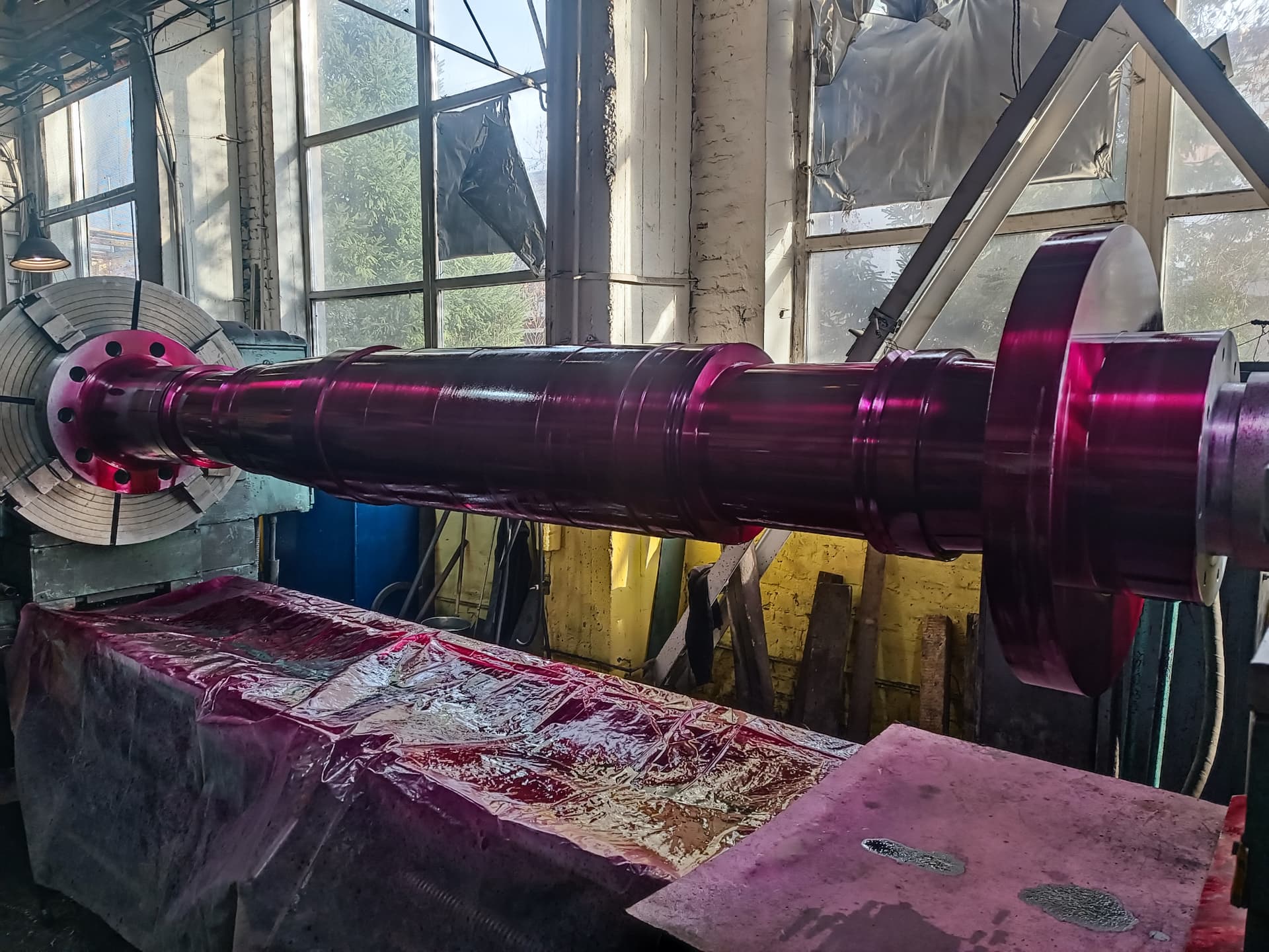
How can you tell that a rotor bar is broken?

Possible signs:

  • a decrease in starting torque;
  • a prolonged acceleration;
  • increased slip;
  • torque pulsations;
  • a rhythmic hum;
  • characteristic components in the current spectrum.

It is advisable to confirm the defect with a special cage test.

Can a motor run with one broken bar?

It can, especially at a light load. But the defect increases the load on the neighbouring bars and can develop quickly.

Why does rotor damage show up more strongly during starting?

During starting, the currents in the rotor and the electromagnetic forces are considerably higher than in steady-state operation.

Why does the rotor overheat?

The causes can be:

  • cage damage;
  • frequent starts;
  • overload;
  • increased slip;
  • reduced voltage;
  • harmonics from the variable frequency drive;
  • poor cooling.

How do you check the shaft for a bend?

The rotor is placed on control supports or centres, and the radial runout is measured with a dial indicator at several cross-sections.

Does the rotor need to be balanced after replacing the bearings?

Replacing the bearings alone does not always change the rotor’s balance. But if machining, a shaft, fan or cage repair was carried out, or there were signs of vibration, the balancing must be checked.

Why does the rotor touch the stator?

Possible:

  • damaged bearings;
  • a deformed shaft;
  • worn fits;
  • displaced end shields;
  • incorrect assembly;
  • frame deformation.

How do you check a wound rotor?

It is necessary to measure the phase resistances and the insulation resistance, measure the inductance, carry out a surge test and inspect the winding, the bandages and the slip rings.

How do you check an armature for an interturn short circuit?

A surge tester, an induction instrument or comparison of the electrical parameters of the coils is used.

Why do the slip rings of a wound rotor spark?

Causes:

  • contamination;
  • runout;
  • incorrect brush pressure;
  • unequal currents;
  • a rotor winding defect;
  • a fault in the starting rheostat.

Why does the motor vibrate after a rotor repair?

Possible:

  • the absence of balancing;
  • shaft deformation;
  • displacement of the core;
  • incorrect fan fitting;
  • assembly errors;
  • an uneven air gap.

Can a crack in an end ring be welded?

Technologically this is sometimes possible, but the material, the design, the speed, thermal deformation and the need for subsequent flaw detection and balancing must be taken into account.

Can a rotor be tested without removing it?

Preliminary diagnostics can be carried out using the current, the vibration, the speed, the slip and the temperature. A complete mechanical and electromagnetic assessment usually requires disassembly.

Which is more important: current analysis or checking the removed rotor?

These methods complement each other. Current analysis shows the behaviour of the machine while it is running, while checking the removed rotor allows its design condition to be assessed directly.

Services of ELEKTROPROMREMONT LLC

ELEKTROPROMREMONT LLC carries out comprehensive diagnostics, defect assessment, repair and testing of the rotors of industrial electrical machines.

The scope of work includes:

  • diagnostics of the squirrel-cage;
  • detection of broken bars;
  • checking the end rings;
  • defect assessment of wound rotors;
  • checking rotor windings;
  • surge testing;
  • insulation resistance measurement;
  • DC resistance measurement;
  • checking armatures;
  • commutator diagnostics;
  • checking field windings;
  • checking damper windings;
  • shaft flaw detection;
  • measurement of the fit surfaces;
  • checking the radial and face runout;
  • shaft repair and manufacture;
  • restoring the fits;
  • repairing squirrel-cage rotors;
  • repairing slip rings;
  • repairing commutators;
  • repairing and rewinding wound rotors;
  • repairing armatures;
  • restoring bandages;
  • repairing fans;
  • dynamic balancing;
  • checking the air gap;
  • no-load testing;
  • load testing;
  • vibration and thermal monitoring after the repair;
  • preparing test reports and technical conclusions.

Conclusion

Testing the rotor is a combination of mechanical, electrical and magnetic operations.

For a squirrel-cage rotor, the following must be assessed:

  • the bars;
  • the end rings;
  • the steel core;
  • the shaft;
  • the fits;
  • the geometry;
  • the fan;
  • the balancing.

For a wound rotor, the following are additionally checked:

  • the winding;
  • the insulation;
  • the interturn condition;
  • the slip rings;
  • the bandages.

For the armature of a DC machine, the main objects of control are:

  • the winding;
  • the commutator;
  • the coil connections;
  • the bandages;
  • the interturn insulation.

The basic diagnostic principle is that a rotor cannot be declared sound based on a single result alone.

In particular:

  • normal phase currents do not always rule out an early-stage cage defect;
  • the absence of a visible crack does not mean the bar is intact;
  • a normal continuity reading does not confirm the soundness of a short-circuited cage;
  • balancing does not eliminate shaft deformation or a cracked ring;
  • repairing the rotor without checking the stator and the air gap may not eliminate the cause of the failure.

A reliable conclusion is formed after analysing the motor’s operation, carrying out instrumental testing, inspecting the removed rotor and performing a verification test after reassembly.

Important disclaimer

This material is for informational purposes. The values, diagnostic methods, scope of work and recommendations given here are general and do not replace the manufacturer’s technical documentation. The final decision for a specific machine is made from its own diagnostics and inspection, taking into account its type, power, design, duty, operating history and applicable standards.

Need a rotor test?

We will carry out a complete rotor diagnosis — from start-up and current spectrum analysis to checking the cage, the shaft and the balancing — and issue a conclusion on further operation or repair.

Get a consultation