What is a synchronous motor?
An AC motor whose rotor, in steady state, rotates at the same speed as the stator’s magnetic field.
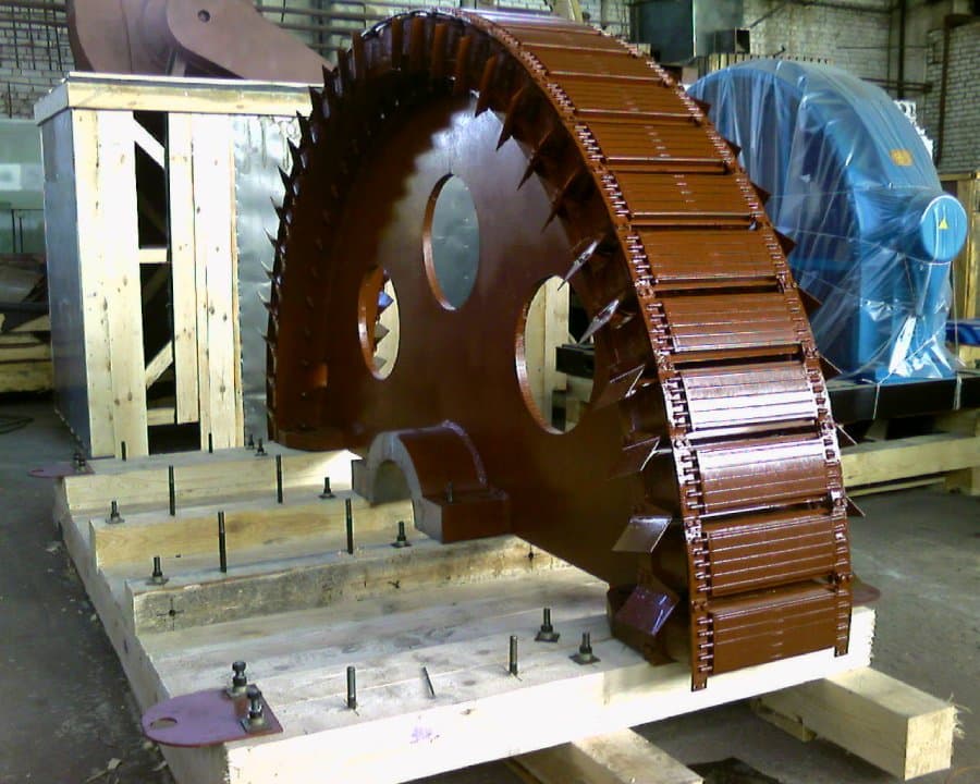
Synchronous motors are among the most important types of AC electrical machines, used in industry, power generation, metallurgy, mining, water supply, chemical production, compressor plants and modern variable-speed drives.
Unlike an induction motor, the rotor of a synchronous machine in steady state rotates at exactly the same speed as the stator’s rotating magnetic field: there is no working slip between rotor speed and the synchronous speed of the field.
Synchronous motors are used to drive:
A separate application is using synchronous machines without mechanical load as synchronous condensers — for reactive power control, voltage support, power-factor improvement and grid stability. Large industrial synchronous motors can have power ratings in the tens of megawatts.
A synchronous machine is a complex electromagnetic system whose operating characteristics are determined not only by the stator winding but also by the rotor design, excitation system, pole shape, air gap, damper cage, load angle, field current, starting conditions, cooling system, bearing condition and mechanical geometry. Repairing a synchronous motor therefore requires a comprehensive restoration of its electrical, magnetic, mechanical, insulation, ventilation and excitation systems.
A synchronous motor is an AC electrical machine whose rotor, in steady state, rotates in synchronism with the stator’s magnetic field. Synchronous speed is defined by the supply frequency and the number of poles:
nₛ = 120f / P
where:
For example, at 50 Hz:
| Number of poles | Synchronous speed |
|---|---|
| 2 | 3000 rpm |
| 4 | 1500 rpm |
| 6 | 1000 rpm |
| 8 | 750 rpm |
| 10 | 600 rpm |
| 12 | 500 rpm |
| 16 | 375 rpm |
| 20 | 300 rpm |
| 24 | 250 rpm |
In normal synchronous operation, actual rotor speed equals these values and is practically independent of mechanical load, as long as the motor does not fall out of synchronism. The rotor field can be produced by a DC winding, permanent magnets, a reluctance rotor design, or a combined magnetic system.
Main types of synchronous motors:
General rated characteristics, duty types and requirements for most rotating electrical machines are set out in IEC 60034-1:2026. Methods for determining the parameters of electrically excited synchronous machines from test results are covered by IEC 60034-4 and IEC 60034-4-1.
The word "synchronous" means that the rotor and the stator’s magnetic field move at the same angular speed. The stator creates a rotating magnetic field, and the rotor has its own magnetic field. In operation, the rotor field "locks" onto the stator field, and the rotor rotates together with it.
Unlike an induction motor:
The operation of an electromagnetically excited three-phase synchronous motor can be described as follows:
When load increases, the rotor does not begin to continuously rotate slower, as an induction motor would. Instead, the angular lag of the rotor’s magnetic axis behind the stator field increases. This angle is called the load angle, torque angle, power angle, or electrical angle δ. As long as the angle stays within allowable limits, the motor remains in synchronism.
A synchronous motor can include:
In general design, the stator of a synchronous motor is similar to that of an induction machine: a frame, an electrical-steel core, slots, teeth, a stator winding, insulation, wedges, bandages, ventilation ducts and temperature sensors.
The stator winding is usually three-phase and can be random-wound or form-wound, single- or double-layer, lap or wave, with round or rectangular wire, low- or high-voltage. Large high-voltage motors use form-wound coils or bars with multi-layer mica ground insulation.
The core is made of thin electrical-steel laminations, insulated from one another to limit eddy currents. In large machines, the core can be built from segments with radial ventilation ducts between packs.
Core condition affects iron losses, no-load current, heating, magnetic symmetry, vibration level, local hot spots and synchronous-operation stability.
Damage to the interlaminar insulation is especially dangerous after rotor-to-stator rubbing, a short circuit, uncontrolled winding burnout, mechanical removal of conductors, or welding work on the core.
The rotor produces the magnetic field that interacts with the stator field. By the principle of flux generation, rotors are divided into electromagnetically excited, permanent-magnet, reluctance, hysteresis and combined types. By magnetic-system geometry, they are salient-pole or non-salient-pole (cylindrical).
A salient-pole rotor has separately distinguishable magnetic poles. Each pole usually consists of a pole body, a pole shoe, a field coil, insulation, fastenings, damper bars and interpole connections.
Salient-pole design is typical of low-speed, multi-pole motors — drives for mills, pumps, compressors, low-speed industrial machinery, and synchronous condensers.
Advantages:
Disadvantages:
The pole shoe distributes magnetic flux, shapes the air gap, affects the field shape, supports the damper bars, and reduces local saturation and synchronous reactances. Its damage can cause field asymmetry, vibration, uneven heating, torque pulsation and a risk of stator rub.
The field coil of a salient-pole rotor can be made from rectangular copper wire, copper busbar, strip conductor, or a rigid multi-turn construction. Coils are connected so neighboring poles alternate: N, S, N... During repair, the number of turns, winding direction, polarity, conductor cross-section, resistance, insulation, geometry, interpole connections and mechanical fastening must all be precisely restored.
A non-salient-pole, smooth, or cylindrical rotor has no separate projecting poles — the field winding is embedded in slots of a solid rotor body. This design is used mainly in high-speed synchronous machines, two- and four-pole motors, compressor drives, and turbomachinery.
Advantages:
Disadvantages:
| Characteristic | Salient-pole rotor | Non-salient-pole rotor |
|---|---|---|
| Construction | Separate projecting poles | Smooth cylindrical rotor |
| Typical speed | Low or medium | High |
| Pole count | Often large | Usually 2 or 4 |
| Air gap | Non-uniform | Relatively uniform |
| Coil repair | Often simpler | More complex |
| Mechanical strength at high speed | Limited | High |
| Typical drives | Mills, pumps, compressors | High-speed compressors |
The choice between salient-pole and cylindrical construction depends primarily on speed, power, mechanical loads and the required number of poles.
The field winding produces the rotor’s constant magnetic field. Field current determines magnetic flux, internal EMF, reactive power, power factor, static stability margin, and rotor heating. Too little field current causes under-excitation, too much causes over-excitation.
Main excitation system options:
DC is delivered to the rotor winding through slip rings, brushes, brush holders and current-carrying bars.
Advantages:
Disadvantages:
Slip rings can be made of copper, bronze, steel or special alloys and must have correct geometry, minimal radial runout, a smooth working surface, reliable insulation and a stable electrical connection to the winding. Typical defects: grooving, burning, ovality, waviness, cracks, loose fastening, insulation breakdown, contamination with copper-graphite dust.
The brush gear includes brushes, brush holders, springs, a rocker ring, flexible leads and insulators. Maintenance checks brush grade, pressure, contact, height, free movement, temperature, sparking and current-sharing uniformity. Excessive pressure causes mechanical wear and heating; insufficient pressure causes sparking, unstable contact and ring burning.
In a brushless system, an exciter is mounted on the same shaft as the main machine: an exciter field winding on the stator, a rotating armature winding, a rotating diode rectifier, the main rotor’s field winding, and sometimes a permanent-magnet pilot exciter. AC produced by the rotating exciter armature is rectified by diodes directly on the rotor and fed to the main field winding.
Advantages:
Disadvantages:
Synchronous-machine test standards contain separate provisions for brushless-excitation machines. Failure of a single diode can cause field-current ripple, rotor heating, vibration, overload of other diodes, loss of synchronism, and inability to start under load.
In a static system, DC is produced by a stationary controlled rectifier and fed to the rotor through slip rings. This provides fast regulation, forcing capability, precise control and rapid field suppression, but retains the brush gear and depends on power electronics and the control system.
An automatic voltage regulator (AVR) can control field current, power factor, reactive power, voltage, stability margin, field forcing and rotor-current limiting — maintaining a target cos φ, reactive power, field current, or bus voltage.
In permanent-magnet synchronous motors, the rotor field is produced by magnets — neodymium-iron-boron, samarium-cobalt, ferrite, or other magnetic materials. Magnets can be placed on the rotor surface, inside the rotor, in special magnetic barriers, or in a combined reluctance-magnetic design.
Advantages:
Disadvantages:
Surface magnets sit on the outer rotor surface: a relatively simple magnetic circuit and small inductive asymmetry, but mechanical retention is difficult and there is a risk of detachment at high speed, requiring a retaining sleeve or bandage.
Interior magnets are embedded inside the rotor stack: better mechanical protection and the ability to use the reluctance torque component, but more complex geometry, more complex repair and high assembly requirements.
Can occur due to overheating, excessive stator current, an incorrect current angle, short circuits, a strong opposing field, mechanical damage, or magnet aging or corrosion.
Symptoms: reduced torque, increased current, uneven back-EMF, vibration, torque ripple, phase-parameter asymmetry.
In a synchronous reluctance motor, the rotor does not necessarily have permanent magnets or a field winding — torque arises from the rotor’s tendency to align with the position of minimum magnetic reluctance. The rotor has different magnetic permeance along the direct axis d and the quadrature axis q; this difference is created by flux barriers, special rotor shaping, anisotropic structure, cutouts and bridges.
Advantages of reluctance synchronous motors:
Disadvantages:
In a hysteresis synchronous motor, torque is created through the rotor’s magnetic hysteresis. Advantages: smooth starting, low noise, uniform torque, precise synchronous speed. Used mainly in low-power drives, clock mechanisms, instruments, audio equipment, and special precision installations.
The damper winding, or amortisseur/starting cage, sits in the pole shoes of a salient-pole rotor and consists of bars connected by short-circuiting rings or segments. Its functions: asynchronous starting, damping rotor oscillations, reducing speed ripple, improving dynamic stability, damping hunting, and stabilizing during load changes. During starting it behaves much like the squirrel cage of an induction motor.
If a synchronous motor has a damper cage, it can be started as an induction motor:
Successful synchronization depends on the load torque, mechanism inertia, voltage, damper-cage condition, field current, the timing of excitation application, rotor angle, and acceleration time.
If a stationary rotor has only a fixed magnetic field, the stator’s rotating field rapidly reverses the direction of electromagnetic torque relative to the rotor, and the average starting torque can be insufficient or close to zero. This is why starting relies on a damper cage, an auxiliary motor, a frequency converter, a special ramp-up system, a starting induction winding, or a ramp from zero frequency.
The converter starts at low frequency — the stator field rotates slowly, and the rotor can stay synchronized with it during acceleration. This gives smooth starting, current limitation, torque control, and the ability to start under load, and is especially important for permanent-magnet motors, reluctance synchronous motors, large compressors, mills and servo systems.
Alternatively, the rotor can be accelerated to near-synchronous speed by an auxiliary motor, after which excitation is applied, the synchronous motor is connected to the supply, and the auxiliary drive is disconnected. To ease starting, guide vanes may also be closed, the compressor unloaded, the process load disconnected, or a pump started against closed or throttled valves.
Successful synchronization requires a sufficiently small speed difference, correct field current, an allowable load, sufficient synchronizing torque, a sound damper system, and correct control. If the motor fails to synchronize, it can continue running asynchronously, draw high current, heat the damper cage, produce torque pulsations, and trip protection.
In steady synchronous operation, slip s = 0, since n = nₛ. But during asynchronous starting, transients, loss of synchronism, or rotor hunting, the instantaneous speed can differ from the field speed — this is not the constant working slip characteristic of an induction motor.
Unlike an induction motor, the rated speed of a synchronous motor will not be, for example, 1480 rpm for four poles at 50 Hz — it will be close to exactly 1500 rpm, allowing for measurement tolerance and grid frequency.
The angle δ is the angle between the rotor field’s magnetic axis and the resultant rotating stator field. At no load the angle is small; as mechanical load increases, the angle grows — the more torque the shaft requires, the more the rotor field lags the stator field. Up to a certain point, a larger angle increases electromagnetic torque, but once the stability limit is exceeded the motor can fall out of synchronism.
In the simplified case of a cylindrical-rotor synchronous machine, electromagnetic power is approximately:
P ∼ (UE / Xₛ) sin δ
where:
This shows that transferred power depends on grid voltage, field current, machine parameters, and the angle between the fields. A salient-pole machine additionally has a reluctance torque component arising from the difference between the d- and q-axis reactances.
The maximum torque beyond which the motor loses synchronism is called the pull-out torque or maximum synchronous torque. If load exceeds this limit, angle δ keeps increasing, the rotor is no longer held by the field, torque impacts occur, speed becomes unstable, stator current rises, and protection must trip the machine.
Causes of loss of synchronism: a sudden overload, a voltage dip, loss of excitation, a rotor short circuit, incorrect regulator operation, faulty rotating diodes, too large a load angle, a supply disturbance, a mechanical shock, or mechanism jamming.
Symptoms: current pulsations, loud noise, torque impacts, active- and reactive-power swings, vibration, unstable speed, damper-cage heating, tripping of the out-of-step protection.
After a load change, the rotor can oscillate angularly around the stator field — hunting, or electromechanical oscillation. Causes: abrupt load changes, a pulsating mechanism torque, weak damping, a faulty damper cage, unstable excitation control, or grid fluctuations. The damper cage is meant to suppress such oscillations.
Mechanical shaft load mainly determines the active power the motor draws. Field current largely determines reactive power. By adjusting excitation, a synchronous motor can operate with a lagging current, near-unity power factor, or a leading current — one of the key advantages of an electromagnetically excited synchronous motor.
With insufficient rotor current, the motor draws reactive power from the grid, and stator current typically lags voltage. Excessive under-excitation raises stator current, increases stator heating, reduces stability margin, and can trip loss-of-excitation protection.
At a certain field current, the reactive component of current can be minimal, power factor approaches unity, and for a given active power, stator current is at its minimum value.
With increased field current, a synchronous motor can deliver reactive power to the grid — stator current leads voltage. This allows it to compensate the reactive power of induction motors, reduce the grid’s reactive burden, and improve a plant’s power factor. Excessive over-excitation can overload the field winding, heat the stator, exceed the allowable field current, and shorten insulation life.
A V-curve shows stator current versus field current at constant mechanical load: at low excitation, stator current is elevated and the motor absorbs reactive power; at optimal excitation, stator current is minimal and power factor approaches unity; at excessive excitation, current rises again and the motor delivers reactive power. The plot resembles the letter V.
A synchronous condenser is a synchronous machine operating with essentially no useful mechanical load that controls reactive power: it supports voltage, compensates reactive power, raises short-circuit power, provides electromechanical inertia, and improves grid stability, particularly with a high share of converter-based generation. Once synchronized to the grid, such a machine behaves electrically like a synchronous motor with no useful load, while controlled excitation lets it regulate reactive power.
High-power synchronous motors can achieve very high efficiency. Losses include stator copper losses, field-winding losses, iron losses, mechanical and windage losses, brush-contact losses, exciter and rotating-rectifier losses, and additional stray load losses. Permanent-magnet motors have no continuous copper losses in a field winding, but can have eddy-current losses in the magnets, bandage losses, and additional harmonic losses from the converter.
Efficiency classes for certain single-speed motors on sinusoidal supply are defined by IEC 60034-30-1:2025 (power from 0.12 to 1000 kW, voltage up to 1000 V, 2, 4, 6 or 8 poles). The standard’s applicability to a specific synchronous motor must be checked against its design and supply conditions.
Advantages of synchronous motors:
Disadvantages:
| Characteristic | Synchronous motor | Induction motor |
|---|---|---|
| Speed | Equal to synchronous | Below synchronous |
| Working slip | Zero | Required |
| Rotor field | Excitation, magnets, or reluctance | Induced currents |
| Starting | More complex | Usually simpler |
| Reactive power | Can absorb or supply | Mainly absorbs |
| Power-factor control | Possible via excitation | Essentially unavailable |
| Rotor | More complex | Squirrel cage often simple |
| Loss of synchronism | Possible | Not applicable |
| Large low-speed drives | Very efficient | Possible, but not always optimal |
| Maintenance | Can be more demanding | Often simpler |
Industrial synchronous motors can operate at 3, 6, 10, 11, 13.8 kV and other special voltages, driving compressors, pumps, mills, blowers, exhausters, rolling-mill equipment and large fans. Features: form-wound stator coils, mica ground insulation, vacuum-pressure impregnation, corona-protection coatings, partial-discharge monitoring, an advanced cooling system, a dedicated excitation system, and complex relay protection.
A low-speed motor has a large number of poles and can couple directly to a mill, compressor, pump, or crusher — eliminating a gearbox and reducing mechanical losses and maintenance, but requiring a large diameter, significant mass, and a reinforced foundation.
High-speed synchronous motors are used for centrifugal and turbo compressors and other high-speed units. Features: a non-salient or special rotor, high-precision balancing, critical-speed control, reinforced bandages, sliding or special rolling bearings, complex cooling, and precise control systems.
Used mainly in large vertical pumps, pumping stations, water-supply systems, irrigation, and hydraulic structures. May have upper and lower guide bearings, a thrust bearing, a dedicated oil system, water cooling, and a hollow shaft. The thrust bearing carries the rotor mass, the pump’s axial thrust, and hydraulic loading.
During repair of an explosion-proof machine, flameproof gaps, frame materials, fastenings, seal type, cable entries, the fan, maximum surface temperature, winding data, the impregnation system, bearing design, and the excitation method must not be arbitrarily changed — repair must follow the documentation and the requirements of the applicable explosion-protection certification.
A converter can control frequency, voltage, stator current, torque, flux, load angle, rotor position, speed, and field current using scalar or vector control, direct torque control, sensorless control, or control with an encoder or resolver.
Precise control uses encoders, resolvers, Hall sensors, inductive or magnetic sensors, or sensorless algorithms. Incorrect rotor-position sensor phasing can cause failure to start, reverse torque, overcurrent, vibration, jerking, magnet demagnetization, or converter failure.
Operation above base speed requires reducing effective magnetic flux (field weakening) — in an electromagnetically excited machine, this is done by reducing rotor current, while in a magnet machine the converter injects a current component that partially opposes the magnet field. Limits: converter voltage, stator current, rotor mechanical strength, heating, demagnetization risk, critical speeds, and bearings.
Possible cooling arrangements:
Air flow, water temperature, heat-exchanger cleanliness, fan rotation direction, pump operation, filter condition, leaks, and condensation must all be monitored.
Synchronous motors use the IEC S-series duty types: S1 (continuous), S2 (short-time), S3 (intermittent periodic), S4 (intermittent periodic with starting), S5 (intermittent periodic with starting and electric braking), S6 (continuous periodic), S7 (continuous periodic with starting and braking), S8 (continuous periodic with speed/load changes), S9 (non-periodic with overloads), S10 (discrete constant loads). General requirements for rated duty types and machine characteristics are set out in IEC 60034-1:2026.
Faults can be grouped into stator, rotor, excitation, damper, mechanical, bearing, ventilation, control, operational, and insulation faults.
A stator interturn fault results from insulation aging, overheating, voltage surges, partial discharges, vibration, poor impregnation, contamination, or coil movement, leading to a local circulating current, overheating, conductor destruction, a phase-to-phase fault, or a ground fault.
A phase-to-phase fault can occur in the slot, in the end-winding, in inter-coil connections, in the terminal box, or where a coil exits the slot — especially dangerous for high-voltage form-wound windings. A stator ground fault is caused by damaged slot insulation, moisture, contamination, a sharp core edge, coil vibration, partial discharges, terminal damage, or overheating. An open stator phase shows up as current asymmetry, reduced torque, pulsations, overheating and inability to synchronize.
A field-winding ground fault can occur relative to the pole core, the rotor body, the shaft, an interpole connection, or a slip ring. A single ground fault does not always immediately stop operation but creates a dangerous precondition for a second ground fault, which can short-circuit part of the winding, cause field asymmetry, trigger vibration, and damage the rotor.
A field-winding interturn fault shows up as reduced resistance, increased current at the same voltage, magnetic-field asymmetry, vibration, and local pole overheating. An open field winding (from interpole-connection fatigue, a poor solder joint, a conductor crack, centrifugal loading, or overheating) causes loss of field, a sharp rise in reactive current, loss of synchronism, and rotor heating.
Loss of excitation is one of the most dangerous faults: causes — exciter failure, a rotor open circuit, brush failure, diode damage, loss of regulator power, thyristor-rectifier failure, or an automation error. Consequences: a shift to asynchronous operation, significant reactive-power consumption, heating of the damper cage and poles, torque ripple, loss of synchronism, and rotor damage.
A rotating-diode fault (open circuit, breakdown, elevated forward resistance, poor heatsink contact, lead crack, loose bolted connection) shows up as unstable excitation, increased vibration, exciter heating, current ripple, and insufficient torque.
A broken damper bar (from frequent or prolonged starts, asynchronous operation, thermal cycling, metal fatigue, or a solder defect) worsens starting, increases synchronization time, and causes hunting and local pole-shoe overheating. A cracked short-circuiting segment causes uneven current distribution, heating of adjacent bars, reduced damping, and joint failure.
Pole looseness is a dangerous mechanical defect (loose bolts, broken wedges, fastening fatigue, corrosion, incorrect assembly, overspeed) that alters the air gap, causes vibration, stator rub, and can lead to catastrophic rotor failure. Pole-coil deformation (centrifugal forces, short circuit, loose fastening, thermal expansion) can lead to rubbing, breakdown to the core, and interturn faults.
Permanent-magnet faults: demagnetization, cracking, corrosion, delamination, displacement, detachment, bandage damage, non-uniform flux. Slip-ring faults: wear, grooving, burning, ovality, runout, cracks, insulation breakdown, loose fastening, contamination.
Excessive brush sparking is caused by the wrong brush grade, insufficient or excessive pressure, ring runout, contamination, an uneven surface, vibration, uneven current sharing, poor seating, or damage to a flexible lead.
A non-uniform air gap (bearing wear, pole looseness, a bent shaft, frame misalignment, incorrect assembly) causes magnetic-field asymmetry, unbalanced magnetic pull, vibration, local heating, and rubbing.
Synchronous-motor overheating can be caused by overload, incorrect excitation, voltage asymmetry, cooling contamination, fan failure, a stator defect, a rotor interturn fault, diode failure, asynchronous operation, frequent starts, elevated harmonics, or mechanical friction.
Increased vibration can be caused by imbalance, misalignment, soft foot, a bent shaft, a non-uniform gap, rotor-field asymmetry, shorted turns, a damper-cage defect, hunting, a loose pole, a bearing defect, resonance, or a pulsating load.
If the motor fails to synchronize, check supply voltage, load torque, acceleration time, the damper cage, field current, the timing of excitation application, rotating diodes, the regulator, phasing, mechanical jamming, and unit inertia. If the motor falls out of synchronism under load, possible causes include excessive load, insufficient excitation, reduced voltage, a rotor-winding defect, faulty diodes, a weak damper cage, mechanical-torque fluctuations, incorrect regulator tuning, or a grid short circuit.
Diagnostics should cover the stator, rotor, excitation system, damper winding, mechanical parts, cooling system, control system, and the unit as a whole.
Check the stator end-windings, bandages, wedges, terminals, contamination, signs of partial discharge, pole coils, interpole connections, damper bars, pole fastenings, slip rings, brushes, diodes, fans, bearings, and heat exchangers.
Stator insulation resistance is measured phase-to-phase and phase-to-ground, plus for auxiliary windings and sensors, taking temperature, humidity, rated voltage, and prior measurements into account. Rotor insulation resistance is checked for the field winding to ground, slip rings to shaft, the exciter, the rotating rectifier, and interpole connections.
DC resistance is measured for the stator phases, field winding, pole coils, interpole connections, and exciter winding, with results referred to a common temperature — asymmetry can indicate an open circuit, a poor joint, shorted turns, or a rewinding error.
A surge (impulse interturn) test is applied to the stator winding, individual coils, pole coils, and the exciter winding, and can reveal interturn shorts, weakened insulation, a turn-count mismatch, or an incorrect connection. A hipot (high-voltage withstand) test checks the dielectric strength of the stator, rotor, auxiliary circuits, and exciter insulation, following a controlled procedure that accounts for insulation condition and history.
Partial-discharge monitoring is especially important for high-voltage windings and can be done offline or online, during operation or after repair — it helps detect internal voids, delamination, slot-section defects, degraded corona protection, and contamination. For machines with converter-fed stator or rotor windings, IEC TS 60034-27-6 on online partial-discharge detection and monitoring was issued in 2026.
After repair, pole alternation polarity must be verified — a single reversed pole causes gross field asymmetry, absence of normal torque, vibration, elevated current, and inability to run synchronously.
Shorted rotor turns are identified by comparing resistance, measuring the voltage drop across coils, monitoring magnetic flux, thermal imaging, vibration analysis, flux-density measurement, special impulse methods, or field-current monitoring.
Rotating diodes are checked for forward conduction, reverse blocking, leakage, breakdown, thermal contact, and mechanical fastening — checking with an ordinary multimeter alone is not always enough to reveal a defect that only shows up under working current or temperature.
The damper cage is checked by visual inspection, dye-penetrant and eddy-current testing, ultrasonic testing, electrical-continuity measurement, thermal imaging during testing, and analysis of the starting characteristic and oscillations.
The air gap is measured at several points around the circumference and along the length, accounting for each pole’s geometry, rotor position, axial offset, and runout on salient-pole machines. Large asymmetry can indicate rotor displacement, a bent shaft, pole looseness, stator deformation, or bearing wear.
Vibration diagnostics can assess imbalance, misalignment, soft foot, resonance, bearings, electromagnetic asymmetry, hunting, pulsating torque, foundation looseness, and coupling defects. Thermal imaging reveals hot poles, overheated brushes, uneven slip-ring heating, defective terminals, overheated bearings, heat-exchanger failure, stator asymmetry, and a faulty diode.
Current and power analysis tracks phase currents, active and reactive power, cos φ, field current and voltage, harmonic content, and fluctuations under changing load. Unstable reactive power can indicate a faulty regulator, an excitation defect, hunting, grid instability, or mechanical oscillation.
Can include cleaning, drying, local insulation repair, wedge replacement, bandage restoration, terminal repair, sensor replacement, rewinding, manufacturing form-wound coils, vacuum or vacuum-pressure impregnation, and core repair.
When recording stator winding data, note the number of slots, poles, and phases, winding pitch, turn count, wire cross-section, the number of parallel conductors and parallel paths, connection scheme, group direction, phase interconnections, sensor placement, coil dimensions, insulation construction, corona protection, and copper mass.
Pole-coil repair can include cleaning, replacing turn and ground insulation, manufacturing a new coil, restoring leads, repairing interpole jumpers, impregnation, testing, and geometry checks. When manufacturing a new coil, the turn count, copper cross-section, winding direction, resistance, dimensions, lead position, cooling scheme, and insulation class must all be restored.
Interpole connections are subject to centrifugal forces, vibration, thermal expansion, and electrodynamic loads — adequate cross-section, flexibility, mechanical fixing, electrical contact, insulation, and cyclic durability must be ensured.
Damper-cage repair can include bar replacement, solder restoration, short-circuiting-segment repair, flexible-jumper replacement, and pole-shoe restoration — replacing a single bar without checking the whole cage may fail to address the root cause.
Slip-ring repair includes turning, grinding, polishing, insulation restoration, ring replacement, lead restoration, balancing, and runout checks; after machining, allowable diameter, surface cleanliness, absence of waviness, and minimal runout must be ensured.
Brushless-exciter repair includes checking the stator and rotating windings, diode and fuse checks, connection repair, insulation checks, balancing, and checking the regulation system.
Permanent-magnet rotor repair requires special safety measures against strong attraction forces, the risk of tool damage, and hazards to electronic devices; possible work includes flux monitoring, magnet inspection, replacement of damaged segments, adhesive restoration, bandage repair, retaining-sleeve restoration, balancing, and back-EMF checks.
Balancing is mandatory after pole repair, coil replacement, damper-cage repair, diode or heatsink replacement, slip-ring repair, fan replacement, bandage repair, machining, magnet replacement, or shaft repair. Large rotors may require low-speed and high-speed balancing, multi-plane balancing, and a mechanical-condition check at operating speed.
Bearing-assembly repair checks shaft journals, fits, bearing brackets, pedestals, shells, oil rings, seals, lubrication channels, axial position, and electrical insulation. Large synchronous motors often use sliding (sleeve) bearings — advantages: high load capacity, suitability for large shafts, good damping, ability to run at high speed, repairability of the shell; faults: babbitt wear, overheating, scoring, oil-film breakdown, oil contamination, incorrect clearance, misalignment, and electrical erosion.
Shaft currents can arise from magnetic asymmetry, shaft voltage, converter-fed operation, incorrect grounding, or damaged bearing insulation. Insulated bearings and shells, shaft grounding, grounding brushes, proper cable shielding, and converter filters are used to address this.
Can include stator and rotor insulation resistance, absorption ratio, polarization index, phase and field DC resistance, surge testing, hipot testing, polarity checks, diode and damper-cage checks, air-gap control, balancing, rotation-direction checks, a starting test, a pull-in-to-synchronism check, field-current and cos φ control, reactive-power measurement, vibration and temperature monitoring, and a load test.
Methods for determining the characteristics and parameters of electrically excited synchronous machines from test results are covered by the relevant parts of IEC 60034.
What not to do:
| Symptom | Possible cause | What to check |
|---|---|---|
| Motor does not start | No starting torque | The damper cage and starting scheme |
| Fails to synchronize | Insufficient excitation | Rotor current |
| Falls out of synchronism | Overload | Mechanism torque |
| High stator current | Incorrect excitation | The V-curve |
| Low power factor | Under-excitation | The excitation regulator |
| Leading current too high | Over-excitation | Rotor current |
| Fluctuating reactive power | Unstable regulator | The excitation system |
| One pole runs hot | Interturn fault | Coil resistance and temperature |
| Brushes spark | Runout or wrong pressure | Rings and brush holders |
| Excitation is unstable | Faulty diode | The rotating rectifier |
| High vibration | Field asymmetry | Poles and rotor winding |
| Vibration after repair | Imbalance | Balancing |
| Rotor hunts | Weak damping | Damper bars |
| Pole-shoe heating | Asynchronous operation | Protection and synchronism |
| Low rotor-to-ground resistance | Moisture or damage | Coil insulation |
| Rings overheat | Poor contact | Brushes and surface |
| Poor starting | Broken damper bar | The cage |
| Noise under load | Large angle δ | Load and voltage |
| Unstable speed from a VFD | Sensor error | Encoder or resolver |
| Low torque from a magnet motor | Demagnetization | Back-EMF |
Check the polarity of all poles, turn count, coil resistance, interpole connections, the damper cage, diodes, field current, the timing of excitation application, and mechanical load.
Check turn count, pitch, connection scheme, parallel paths, phasing, core condition, air gap, voltage, field current, and mechanical load.
Possible causes: an interturn fault, a poor interpole connection, incorrect conductor cross-section, a contact defect, a partially shorted coil, or impaired cooling.
Check field current, the automatic regulator, brushes, rings, diodes, the exciter winding, shorted turns, and grid voltage.
Possible causes: the wrong grade, insufficient seating, incorrect pressure, sticking in the brush holder, an uneven ring surface, uneven brush length, or incorrect material polarity for the operating conditions.
Check load peaks, voltage dips, regulator operation, loss of brush contact, rotating diodes, mechanism fluctuations, compressor surges, protection, and the damper cage.
Synchronous-motor protection can include:
Monitoring systems can use Pt100/Pt1000 sensors, thermocouples, PTC sensors, vibration sensors, axial-displacement sensors, air-gap sensors, field-current sensors, shaft-voltage sensors, partial-discharge sensors, water-flow sensors, oil-pressure sensors, and rotor-position sensors.
Routine maintenance regularly checks stator currents, field current and voltage, active and reactive power, cos φ, stator and rotor temperature, bearings, vibration, brushes, rings, diodes, the cooling system, insulation resistance, air gap, foundation condition, alignment, and regulator operation.
An AC motor whose rotor, in steady state, rotates at the same speed as the stator’s magnetic field.
As load increases, the angle between the rotor and stator fields changes, not the constant rotation speed.
In normal steady-state operation, slip is zero.
By a DC winding, permanent magnets, or a reluctance rotor design.
Not every one can. Starting may require a damper cage, a frequency converter, or an auxiliary drive.
A short-circuited bar system in the poles that assists starting and damps oscillations.
In a brushless system, rotor current is produced by an exciter and a rotating rectifier without operating contact brushes.
Over-excitation is operation with increased rotor current, letting the motor deliver reactive power to the grid. Under-excitation is operation with reduced rotor current, during which the motor absorbs reactive power.
Yes. An over-excited motor can compensate the reactive power of other loads on the grid.
A state in which the rotor can no longer rotate together with the stator field — due to overload, insufficient excitation, a voltage drop, or a rotor fault.
A salient-pole rotor has separate projecting poles and is used mainly at lower speeds; a cylindrical rotor is smooth and suited to high speeds.
They rectify the exciter’s current and feed DC to the main rotor field winding in brushless systems.
In some cases magnets are replaced, re-bonded, or re-magnetized, but this requires special technology and safety measures.
No. Interturn insulation, the rotor, excitation, diodes, mechanical condition, and load behavior must all be checked.
Electropromremont LLC performs comprehensive diagnostics, repair, rewinding, and testing of industrial synchronous electrical machines.
The scope of work can include:
A synchronous motor is an AC electrical machine whose rotor, in steady state, rotates exactly at the speed of the stator’s magnetic field. Its defining feature is the absence of working slip. Electromagnetic torque arises from the interaction of the stator’s rotating field and the rotor’s magnetic field; when mechanical load changes, it is not the speed that changes, but the rotor’s angular position relative to the stator field.
Synchronous motors offer important advantages:
At the same time, such a machine requires monitoring of the stator winding, pole coils, damper cage, excitation system, slip rings, brushes, rotating diodes, air gap, balancing, bearings, cooling system, excitation regulator, and out-of-step protection.
A synchronous motor must be repaired as a single electromagnetic, mechanical, insulation, and control system, in which the condition of even one pole, one diode, or one damper bar can determine the performance of the entire machine.
Replacing bearings without checking the air gap, rewinding the stator without diagnosing the rotor, or repairing the excitation system without testing pull-in to synchronism does not deliver predictable reliability.
A proper repair should include:
This article is for general informational purposes. The specific choice of synchronous motor, excitation system, starting method, protection, winding data, rotor current, cooling method, and repair technology must be based on the manufacturer’s documentation, factory drawings, the rated nameplate, electromagnetic calculations, the excitation-system diagram, mechanism characteristics, grid conditions, actual operating duty, ambient conditions, explosion-protection requirements, applicable standards, and the results of professional diagnostics.
Without engineering justification, it is not permitted to change the number of stator or pole turns, conductor cross-section, polarity, the excitation scheme, fit diodes with different ratings, increase rotor current or speed, change the air gap, the damper-cage design, the cooling system, permanent-magnet materials, or protection settings, or operate the machine without loss-of-excitation and out-of-step protection.
Work on high-voltage, explosion-proof, high-speed, magnet, and large-frame synchronous motors must be carried out by qualified personnel using special tooling, controlled processes, calibrated measuring equipment, and appropriate test rigs.
This material is for informational purposes. The values, diagnostic methods, scope of work and recommendations given here are general and do not replace the manufacturer’s technical documentation. The final decision for a specific machine is made from its own diagnostics and inspection, taking into account its type, power, design, duty, operating history and applicable standards.
We handle defect inspection, stator, rotor and excitation-system checks, rewinding, damper-cage repair, balancing, and acceptance testing matched to your machine’s design.