What is a turbogenerator?
A high-speed synchronous generator driven by a steam or gas turbine.
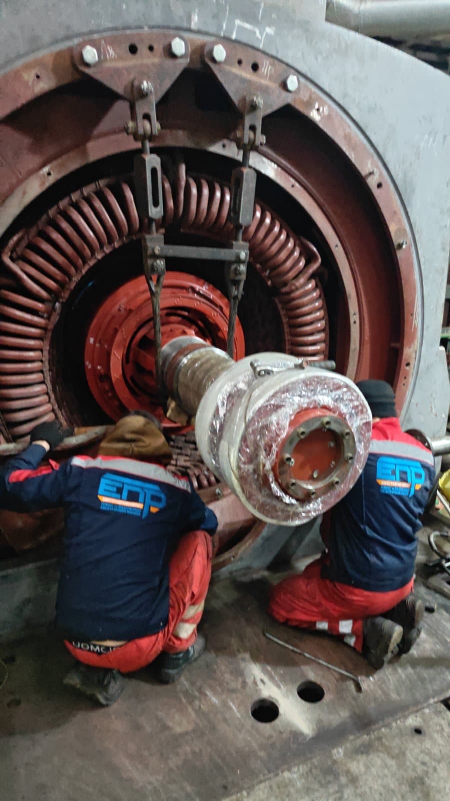
A turbogenerator is a high-speed synchronous generator that converts the mechanical energy of a steam or gas turbine into three-phase AC electrical energy.
Turbogenerators are the primary electrical machines of thermal power plants, nuclear power plants, combined heat and power plants, combined-cycle plants, gas-turbine power blocks, industrial power installations, and large standalone power stations.
Unlike slow-speed hydrogenerators, turbogenerators run at high rotational speed. On a 50 Hz grid, a two-pole turbogenerator has a synchronous speed of 3000 rpm, and a four-pole one runs at 1500 rpm.
The high speed dictates the machine’s characteristic design:
IEC 60034-3:2020 sets out special requirements for three-phase synchronous generators of 10 MVA and above driven by steam or gas turbines, supplementing the general requirements of IEC 60034-1.
A turbogenerator consists of a stationary stator and a high-speed rotor. The rotor carries a DC field winding that produces a magnetic field rotating together with the rotor. The stator core slots hold a three-phase winding — the rotating field crosses its conductors and induces a three-phase EMF.
Synchronous speed:
n = 120f / p
where:
| Number of poles | Synchronous speed (50 Hz) |
|---|---|
| 2 | 3000 rpm |
| 4 | 1500 rpm |
Turbogenerator output is controlled by two main actions: steam or gas flow to the turbine controls active power, and field current controls reactive power and voltage.
The name "turbogenerator" refers not to a distinct electromagnetic principle but to the type of prime mover and the generator’s construction — it is a synchronous generator designed to run together with a steam or gas turbine.
Compared with a hydrogenerator, it has:
In a steam-turbine unit, conversion proceeds in sequence:
In a gas-turbine plant, mechanical energy is produced by hot gases expanding through the gas turbine.
The turbogenerator rotor carries a field winding fed with DC, which produces a magnetic field with north and south poles. As the rotor turns, the magnetic flux shifts position relative to the stator slots, and three sinusoidal EMFs, offset from each other by 120 electrical degrees, are induced in the three-phase stator winding.
Once the generator is synchronized to the grid:
The rotor field rotates at the rotor’s mechanical speed, while the stator current field rotates at synchronous speed. In steady state, these fields rotate at the same speed, so the rotor has no slip relative to the main rotating field, unlike an induction motor.
Turbogenerator nameplate parameters include:
Apparent power of a three-phase generator:
S = √3UI
Active power: P = √3UI cos φ
Reactive power: Q = √3UI sin φ
Relationship between the powers: S² = P² + Q²
where U is the line voltage, I is the line current, and cos φ is the power factor. The turbine determines how much active power reaches the grid; the excitation system largely determines the exchange of reactive power.
The stator is the machine’s stationary part, consisting of an outer frame, core-fastening elements, a core, a three-phase winding, an end-winding support system, ventilation ducts, temperature sensors, current leads, and gas or water piping.
The stator must withstand electromagnetic forces, short-circuit forces, thermal expansion, core and end-winding vibration, internal hydrogen pressure, and dynamic loads during faults.
The frame is usually a rigid welded structure that supports the core, carries mechanical loads, seals the gas volume, houses the coolers, and transfers weight to the foundation. In a hydrogen-cooled turbogenerator, the frame is a gas-tight vessel, so its condition cannot be assessed merely as that of an ordinary electrical-machine frame — welds, flanged joints, seals, inspection covers, cracks, corrosion, deformation, and tightness are all checked.
The core is built up from segments of electrical steel, insulated from each other to limit eddy currents, and includes teeth, slots, the back-iron, ventilation ducts, finger plates, pressure plates, and clamping elements. The core is subject to alternating flux, electromagnetic vibration, local heating, axial and radial forces, and end-region leakage flux effects.
Typical core defects: loosened lamination pressure, damaged interlaminar insulation, local shorts between laminations, melted tooth tips, mechanical marks from the rotor, pack vibration, loosened finger plates, and overheated end packs. An interlaminar fault creates a local eddy-current loop, which can cause intense local heating, winding-insulation destruction, melted active steel, and a stator failure.
The stator winding is a three-phase, high-voltage winding built as bars, half-coils, or form-wound coils. Large turbogenerators typically use two-layer bar windings. A bar consists of transposed strand conductors, ground-wall insulation, a semiconducting slot coating, corona-protection coatings, water-cooling ducts (in water-cooled designs), lead terminals, and water fittings.
Strand conductors within a bar occupy different positions relative to the slot field. Without transposition, they would develop different induced voltages and circulating currents. Transposition periodically changes each conductor’s position and reduces circulating currents, stray losses, and uneven heating. One common scheme is the Roebel transposition.
The insulation system must withstand the operating phase voltage, surge overvoltages, partial discharges, thermal cycling, electromagnetic vibration, radial and axial forces, moisture, contamination, prolonged heating, and fault currents. The ground-wall insulation is usually based on mica tapes, glass fabric, an epoxy resin system, and semiconducting/stress-grading coatings.
A conductive or semiconducting corona-protection coating is applied to the straight slot section of the bar, ensuring uniform contact with the grounded core, reducing local field stress, and preventing slot discharges. Its damage can cause slot-discharge activity, ozone generation, insulation erosion, and a white or gray powdery deposit.
Where the bar exits the slot, surface potential must transition gradually from the core’s potential to the conductor’s potential — a semiconducting stress-grading coating is used for this. Defects in this zone can lead to corona discharges, surface erosion, tracking, and local heating.
End-windings connect the slot sides of the bars and form the three-phase circuit. They are subject to significant electrodynamic forces, especially during external short circuits, out-of-phase closing, phase-to-phase faults, large transient currents, and frequent unit starts. The bracing system can include support rings, glass-laminate brackets, spacer blocks, cord ties, composite elements, and lashings.
If the natural frequency of the components approaches the electromagnetic excitation frequency, resonance can occur — loosened bracing, insulation abrasion, conductor fatigue cracks, cooling-water leaks, and phase-to-phase faults. Flexible operating regimes with frequent load cycles raise the mechanical-stability demands on end-windings; Siemens Energy separately addresses the impact of modern grid duty and cyclic operation on the design and life of turbogenerator end-windings.
A turbogenerator rotor has a cylindrical, non-salient-pole design and is usually machined from a single forging of alloy steel. The forging forms the rotor body, winding slots, teeth, bearing journals, coupling ends, retaining-ring fits, ventilation ducts, and coupling seats. The solid-forged construction is required because of extremely high centrifugal loading.
Centrifugal stress rises with radius and with the square of angular speed. That is why, at 3000 or 3600 rpm, the rotor is made with a relatively small diameter and great axial length, from high-quality forgings, with carefully controlled fillet radii and minimized stress concentrations.
The field winding sits in the longitudinal slots of the rotor body and is made mainly of copper strip or profiled conductors. The insulation system includes slot and turn insulation, packing, side liners, end-winding insulation, and spacer blocks. The winding must withstand DC field current, centrifugal forces, thermal expansion, cyclic loading, vibration, field forcing, and asynchronous operation.
Slot wedges hold the conductors in the slots and can also help form damper circuits, dissipate heat, and distribute mechanical loads. Wedge defects: loosening, displacement, cracks, erosion, overheating, contact loss.
The rotor winding’s end-turns emerge from the slots and are subject to large centrifugal forces, so they are held by massive retaining rings — one of the most critical components of the turbogenerator. A ring must have high mechanical strength, adequate ductility, resistance to fatigue and stress-corrosion cracking, fit stability, and controlled residual stresses.
Possible defects: cracks, stress-corrosion cracking, fretting, loosened fit, deformation, local overheating, electrical burning, mechanical damage during removal, and fatigue failure. Failure of a retaining ring at operating speed can be catastrophic, so it is inspected using nondestructive testing methods appropriate to its design, material, and manufacturer requirements.
In a system with static excitation, DC is fed to the rotor through slip rings, brushes, brush holders, and rotor current leads. Typical slip-ring defects: wear, ovality, runout, grooving, burning, contamination, and brush overheating.
A brushless exciter is mounted on the same shaft as the turbogenerator and can include a pilot exciter, a main AC exciter, a rotating armature winding, a rotating diode bridge, current leads to the rotor winding, and an automatic voltage regulator.
Advantages: no power brushes, less carbon dust, lower operating costs. Disadvantages:
A static system supplies the rotor winding through slip rings from a controlled power-electronic converter and can include an excitation transformer, a thyristor bridge, an automatic voltage regulator, a forcing system, overvoltage protection, a field-suppression device, and a discharge resistor. Advantages: high speed of response, fast forcing, precise regulation, effective field suppression, and a favorable effect on grid stability.
The automatic voltage regulator (AVR) adjusts field current to maintain terminal voltage, reactive power, power factor, and a target reactive-power exchange mode. Additional functions: minimum and maximum excitation limiting, rotor- and stator-current limiting, a power-system stabilizer, loss-of-excitation protection, and forcing during an emergency voltage dip.
The rotor’s magnetic axis and the resultant stator field have a certain angular offset, called the load angle, torque angle, internal angle, or angle δ. As the turbine’s mechanical power increases, the angle grows; if it exceeds an allowable limit, the generator can lose synchronism.
In a simplified model, a synchronous machine’s active power is related to the sine of the load angle:
P ≈ EU/X · sin δ
where E is the internal EMF, U is the grid voltage, X is the synchronous reactance, and δ is the load angle. This simplified equation is useful for understanding stability but does not replace a full calculation for a real turbogenerator.
As excitation increases, the generator usually delivers more reactive power to the grid; as excitation decreases, it can absorb reactive power. However, the allowable operating region is limited by rotor heating, stator heating, end-region heating, stability, minimum excitation, maximum current, and turbine constraints.
The capability curve shows the allowable combinations of active and reactive power. Its boundaries can be set by rated stator current, allowable rotor current, end-pack heating, the stability limit, minimum excitation, maximum turbine power, and cooling-medium pressure and temperature. Operating outside the allowable diagram may not immediately trip protection, but it accelerates machine aging.
Depending on power and design, generators use air cooling, hydrogen cooling, direct hydrogen cooling of the rotor, water cooling of the stator, and combined hydrogen-water or air-water cooling. IEC 60034-3 covers special requirements for air-, hydrogen-, and liquid-cooled turbogenerators.
Air-cooled turbogenerators are structurally simpler: no hydrogen system, simpler sealing, lower explosion risk, simpler maintenance. Downsides — greater windage losses, lower heat-removal capacity, and larger dimensions for the same power.
Modern air-cooled generators can reach hundreds of MVA. Siemens Energy states a rating of up to 370 MVA and efficiency up to 98.9% for one of its air-cooled series.
Hydrogen is used as the cooling gas inside the sealed casing. Compared with air, it has low density, lower windage losses, high thermal conductivity, good heat capacity, and lower aerodynamic noise. GE Vernova cites hydrogen’s low density, high specific heat, and high thermal conductivity as the main reasons for using it in large generators.
Cooling effectiveness and windage losses depend on hydrogen purity. A drop in purity from air ingress increases the gas mixture’s density, raises windage losses, lowers efficiency, and creates an explosive mixture. Hydrogen purity, pressure, temperature, humidity, and leakage are therefore monitored.
A mixture of hydrogen and air at certain concentrations is explosive. The casing is therefore never filled with hydrogen directly from an air-filled state — an intermediate gas, usually CO₂, is used for purging: air is displaced by CO₂, then CO₂ is displaced by hydrogen (and in reverse when emptying). These operations must follow the approved procedure of the specific plant and manufacturer.
Heated hydrogen or air passes through heat exchangers (gas coolers) containing tube bundles, water boxes, headers, seals, and a condensate-drain system. Typical defects: fouled tubes, corrosion, leaks, air locks, insufficient water flow.
In high-power machines, stator bars can contain hollow conductors or tubes through which specially treated water circulates. Direct heat removal allows a higher allowable current, a smaller temperature gradient, higher unit output, and smaller dimensions. Siemens Energy notes that water-cooled bars reduce thermomechanical stress in the end-windings, and combining a GVPI stator with water cooling produces uniform temperatures.
Cooling water must have controlled conductivity, pH, oxygen content, temperature, flow rate, pressure, and cleanliness. Elevated conductivity increases leakage currents, low flow causes local overheating, and contamination or corrosion products can narrow or block the channels. Water is fed to the bars through ring headers, insulating hoses, fittings, and hollow terminals, which must simultaneously provide hydraulic tightness, electrical insulation, and vibration resistance.
A stator water leak (from a fatigue crack in a hollow conductor, a soldering defect, fitting damage, or vibration) can lead to reduced insulation resistance, a ground fault, hydrogen-atmosphere contamination, and a severe stator failure. In a hydrogen-water machine, hydrogen pressure can exceed water pressure, so hydrogen can enter the stator cooling circuit through a defective hollow conductor — signs: gas appearing in the expansion tank, a pressure change, gas-separator activity. For aging water-cooled generators, hydrogen ingress into stator bars is a known risk, which is why specialized leak-monitoring systems are used.
In a hydrogen-cooled turbogenerator, the shaft exits the sealed casing, and oil seals are used to retain the hydrogen. Seal oil is supplied at a pressure higher than the gas pressure. The system must prevent hydrogen escape, limit air ingress, maintain a stable differential pressure, and provide pump redundancy.
Seal-oil system faults: low pressure, unstable differential pressure, oil contamination, worn seal rings, clogged passages, pump failure, hydrogen ingress into the oil system. A seal failure can quickly create a hazardous situation, so the system has backup power sources and emergency algorithms.
Turbogenerators mostly use sliding (journal) bearings, consisting of a housing, a shell, a babbitt layer, oil channels, seals, an oil-supply system, and temperature and vibration sensors. During rotation, the shaft forms a hydrodynamic oil film and must not directly contact the babbitt under normal operation. The film can break down due to low oil pressure, insufficient viscosity, contamination, overload, misalignment, or incorrect clearance.
Some installations use high-pressure jacking oil at slow-roll or turning-gear speed, which lifts the shaft and reduces the risk of dry friction, babbitt damage, and scoring.
Shaft voltages (from magnetic asymmetry, residual magnetism, the excitation system, or static charges) can drive currents through the bearings, causing pitting, babbitt burning, and oil-film breakdown. To break the circuit, one bearing or its components may be electrically insulated.
After the turbine stops, the rotor remains hot for a long time; if it stays still, uneven cooling can cause a temporary thermal bow. The turning gear slowly rotates the shaft during cooldown, warm-up, start preparation, and maintenance operations.
The turbine-generator rotor train has natural bending-mode frequencies. Passing through the corresponding speed produces resonance — such a speed is called a critical speed. The rotor train is designed so the operating speed does not coincide with a dangerous critical speed and so critical speeds are passed through in a controlled manner, with allowable amplitude and sufficient damping.
A turbogenerator rotor requires high-precision balancing. Imbalance can arise from forging non-uniformity, winding displacement, slot-wedge repair, retaining-ring replacement, thermal instability, or contaminated ventilation ducts. Large rotors may require low-speed and high-speed balancing, thermal balancing, and control of mechanical and electrical runout.
A rotor can have acceptable vibration when cold but show increased vibration when excitation is applied or when it heats up — this is called thermal bow or rotor thermal sensitivity. Causes: uneven thermal expansion of the turns, an interturn fault, restricted conductor sliding in the slots, ventilation asymmetry, or differing end-winding stiffness.
The rotor can be cooled at the surface, through axial or radial ducts, via subslot ventilation, with direct hydrogen cooling of the conductors, or with a combined scheme. Clogged ducts cause turn overheating, uneven thermal expansion, rising vibration, and accelerated insulation aging.
Before connecting a generator, phase sequence, frequency, voltage magnitude, and phase angle must all match. A synchronizing error creates a severe electromagnetic shock: high currents, an impact torque, coupling damage, stator-winding displacement, end-winding deformation, and misalignment of the rotor train.
Phase-current asymmetry creates a negative-sequence magnetic field that, relative to the rotor, rotates at high relative speed and induces currents in the rotor surface, slot wedges, retaining rings, and teeth — this causes rapid heating of the rotor surface, wedge damage, and retaining-ring overheating.
On loss of excitation, the generator can continue rotating while drawing reactive power from the grid — the machine shifts into a hazardous asynchronous mode, causing heating of the rotor and stator end region, instability, power swings, and protection tripping.
Faults can be grouped into stator-winding defects, core defects, rotor defects, excitation-system defects, cooling faults, bearing faults, sealing failures, mechanical defects, current-lead damage, and protection/automation faults.
A partial discharge is a localized electrical discharge that does not bridge the full insulation thickness between conductor and ground. It can occur in an internal void, between layers, at the boundary between insulation and copper, in the slot clearance, or on the end-winding surface. Signs: pulse-type electrical signals, ozone, a characteristic smell, white powder, erosion, blackening, and surface tracking.
If a bar is not sufficiently clamped in the slot, it vibrates under electromagnetic forces, the semiconducting coating wears away, clearance increases, and slot discharges appear. Causes of looseness: material shrinkage, wedge aging, weakened wedging system, incorrect repair.
A stator winding ground fault is caused by aging of the ground insulation, partial discharges, local overheating, contamination, moisture, core damage, vibration, or a water leak; consequences depend on the neutral-grounding method, defect location, and protection-clearing speed.
A phase-to-phase fault is usually accompanied by a very large current and can occur in the end-windings, in connection areas, in the current leads, or in the terminal box — possible consequences: winding destruction, end-winding deformation, melted copper, fire, and significant unit downtime.
A rotor interturn fault reduces the number of effective turns in part of the winding and creates magnetic asymmetry; signs — increased vibration with excitation, a change in field current, uneven heating, a change in the open-circuit characteristic, and the appearance of thermal bow.
A single rotor-winding ground fault does not always produce a large current, since the excitation circuit can be isolated from ground, but it is still dangerous: a second fault at another point can short-circuit part of the winding and cause severe magnetic asymmetry, local overheating, vibration, and arcing. Protection or monitoring for a first ground fault in the rotor circuit is therefore used.
Critical zones for rotor cracks: slot teeth, journals, fillets, the central bore, retaining-ring fits, and the coupling section; causes — fatigue, thermal cycling, corrosion, forging defects, overspeed.
Main causes of turbogenerator vibration: imbalance, misalignment, thermal bow, mechanical rubbing, bearing defects, foundation looseness, oil-film instability, a shaft crack, rotor shorted turns, electromagnetic asymmetry, and resonance.
Rotor rubbing can occur at seals, internal components, gas baffles, the stator, bearing seals, current leads, or fan components; signs — new vibration harmonics, a phase shift, local heating, noise, and an unstable shaft-deflection pattern.
Bearing defects: babbitt damage, fatigue spalling, scoring, overheating, a loose shell, distorted geometry, insufficient clearance, electrical erosion, oil-wedge instability. Hydrogen entering the oil system through the seals causes gas saturation, foaming, and explosive concentrations in auxiliary systems — monitoring of gas content and ventilation is required.
Comprehensive diagnostics covers operating-history analysis, review of faults and startups, visual inspection, stator electrical testing, rotor diagnostics, core testing, partial-discharge measurement, water-circuit monitoring, tightness testing, vibration analysis, bearing inspection, oil analysis, excitation-system checks, and functional testing of protection.
Before disassembly, gather operating hours, number of starts, number of trips, overload history, asymmetry data, under-excitation episodes, loss-of-excitation events, peak temperatures, vibration trends, hydrogen purity, water flow rates, partial-discharge history, and previous repairs. What matters is not just the absolute result, but the trend over time.
Insulation resistance is measured for the stator winding to ground, individual phases (if the scheme permits), the rotor winding, the excitation system, and bearing insulation; readings are referred to comparable conditions accounting for temperature and humidity.
The polarization index is the ratio of the insulation resistance after a longer voltage application to its initial value — it helps assess moisture, contamination, and overall insulation condition, though for modern low-capacitance systems interpretation must account for construction and manufacturer instructions.
A hipot test checks the dielectric strength of the insulation — power-frequency AC, DC, resonant test sets, or very-low-frequency methods may be used, depending on what the applicable procedure permits; the test voltage is selected based on rated voltage, age, insulation type, and repair scope.
Dissipation-factor (tan δ) measurement helps assess bulk-insulation condition, voids, moisture ingress, delamination, and contamination — the absolute value, its change with voltage, differences between phases, and multi-year trends are analyzed.
Partial-discharge measurement can be done offline or online, on individual phases, under load, and at different excitation levels, evaluating amplitude, phase-resolved pattern, polarity, pulse shape, and trend. Partial discharge cannot be assessed by a single numeric level alone, without analyzing the signal type and machine history.
Slot wedges are checked by tapping, mechanical assessment, an electromagnetic scanner, displacement measurement, or an automated mapping system — the result can be a map of tight, loose, and void zones.
The core is tested using ring-flux magnetization, thermal imaging, low-flux electromagnetic testing, EL CID or similar methods, and local measurement — the goal is to find interlaminar shorts, local currents, and overheating risk.
In the ring-flux test, a temporary magnetizing winding produces flux in the core while temperature is monitored — a local hot spot can indicate an interlaminar fault. Low-flux methods can reveal local fault currents at a much lower magnetization level, with a smaller source, and allow automated scanning.
Applied methods include insulation-resistance measurement, ground-fault monitoring, DC-resistance measurement, an impedance test, voltage-drop measurement, RSO, a flux probe, thermal testing, nondestructive testing of the forging, retaining-ring inspection, and high-speed balancing.
The Recurrent Surge Oscillograph (RSO) method is used to detect asymmetry and interturn faults in the rotor winding — a pulse signal is applied from different winding ends and the reflected waveforms are compared. In an impedance test, AC voltage is applied to the winding and current, voltage, impedance, and losses are measured — a change in behavior at different rotor positions or voltage levels can indicate an interturn defect.
A flux probe is installed in the air gap and measures magnetic flux during operation, allowing detection of field asymmetry, shorted turns, and defects that only appear under centrifugal force and operating temperature.
Water-cooled bars are tested with hydraulic, pneumatic, and vacuum methods, helium leak testing, pressure-decay checks, and individual bar testing — pneumatic tests require accounting for the high stored energy of compressed gas.
Uneven flow through the bars can indicate clogging, duct deformation, a gas lock, or oxide deposits — absolute flow, pressure drop, inlet/outlet temperature, and neighboring-bar values are compared. Water chemistry analysis covers conductivity, pH, dissolved oxygen, copper, iron, and corrosion products — a sudden change can be the first sign of an internal defect.
Vibration diagnostics tracks absolute bearing-housing vibration, relative shaft vibration, phase, orbit, spectrum, shaft-centerline position, and changes with load, excitation, and temperature — it is especially important to distinguish mechanical imbalance, thermal bow, misalignment, an electromagnetic defect, and oil-film instability. During run-up and coastdown, amplitude, phase, rotational speed, passage through critical speeds, and orbit are recorded — this data often helps distinguish imbalance from resonance or thermal deformation.
IEC 60034-4-1:2018 describes methods for determining the characteristics of three-phase synchronous machines from 1 kVA, though some tests need a special approach for brushless systems (open-circuit and short-circuit characteristics, reactance and time-constant determination, heating checks, and regulation characteristics).
Differential protection compares currents at different ends of a protected zone — an internal fault produces a difference exceeding the allowable value, enabling fast detection of phase-to-phase faults and internal damage.
If steam or gas flow stops but the generator stays connected to the grid, it shifts into motoring mode and begins driving the turbine, which can damage the blades. Reverse-power protection trips the generator on sustained active-power consumption from the grid.
Negative-sequence protection evaluates the negative-sequence current and its thermal effect on the rotor, usually applying an integral characteristic of the form I₂²t, since the allowable duration depends on the level of asymmetric current.
Overexcitation of the core is related to the voltage-to-frequency ratio: elevated V/Hz increases magnetic flux, causing saturation, core overheating, heating of structural parts, and insulation damage.
The scope of a planned repair depends on design, operating hours, number of starts, monitoring results, insulation condition, vibration, manufacturer recommendations, and fault history. Work can range from no rotor removal, to rotor removal, to partial winding disassembly, replacement of individual bars, or a complete stator rewind or rotor rewind.
The rotor has a large mass, considerable length, and a small air gap. Removal uses special beams, dollies, sliding supports, shaft extenders, and hydraulic equipment, taking care to avoid a rotor-to-core impact, end-winding damage, or excess loading on the journals.
Core repair can include cleaning, locally separating shorted laminations, restoring interlaminar insulation, removing melted steel, fitting repair inserts, replacing teeth, restoring finger plates, re-pressing, or a full core replacement. Electromagnetic testing is always repeated after a core repair.
Stator winding repair can cover corona-protection repair, restoring bracing, replacing hoses, re-soldering leads, replacing one bar or a group of bars, replacing the entire winding, restoring phase connections, and repairing current leads.
Bar replacement: marking, removing the end-winding bracing, disconnecting electrical and water connections, removing wedges, extracting the bar, inspecting the slot, repairing the core, checking the new bar, inserting it, restoring the wedging, making electrical and hydraulic connections, restoring corona protection, re-bracing the end-winding, and electrical and hydraulic testing.
A complete stator rewind is needed for systemic aging, numerous defects, severe damage, insufficient remaining insulation life, or a power upgrade. Rewinding can also modernize the insulation system, transposition, the water-cooling system, end-winding bracing, corona protection, and slot-wedge design.
Can include cleaning, insulation checks, local lead repair, contact-connection repair, repacking or replacing conductors, replacing slot insulation, rewinding, replacing wedges, end-winding repair, retaining-ring replacement, ventilation repair, slip-ring repair, balancing, and high-speed testing.
Before disassembly for a rewind, record the number of slots and turns, conductor geometry, connection scheme, interturn insulation, ventilation ducts, packing position, and the thermal-expansion compensation system. The new winding must provide electrical symmetry, mechanical stability, free controlled thermal movement, and the absence of thermal bow.
Because of the interference fit, a retaining ring cannot be removed by ordinary mechanical pulling — depending on design, controlled induction heating, special heaters, or hydraulic equipment with temperature and displacement control is used. Overheating can change the material’s properties or damage the insulation.
Slip-ring repair can include turning, grinding, polishing, restoring grooves, insulation repair, ring replacement, runout checks, and balancing; after machining, brush-grade suitability for the current-loading regime is verified. Gas-cooler repair can include cleaning, flushing, eddy-current testing, hydraulic testing, plugging defective tubes, or replacing the tube bundle — plugging too many tubes reduces cooling capacity and requires a thermal calculation.
Bearing repair includes babbitt inspection, dye-penetrant and ultrasonic bond testing, geometry and clearance checks, scraping, re-babbitting, machining, oil-channel inspection, and alignment. Alignment of the rotor train must account for the cold condition, thermal growth, support rise, the oil wedge, and operating temperatures — the cold, geometrically concentric position is not always the correct operating position.
The test package can include insulation-resistance measurement, polarization index, phase and rotor-winding DC resistance, tan δ, partial discharge, hipot testing, core inspection, hydraulic testing, flow measurement, casing and seal tightness checks, rotor balancing, runout control, bearing-insulation and excitation-system checks, protection testing, start-up testing, vibration analysis, and a load test.
Hydrogen-casing tightness is checked for the frame, covers, flanges, current leads, gas coolers, shaft seals, and piping using pressure-decay monitoring, local leak searching, soap solution, a gas analyzer, the helium method, or an ultrasonic detector.
Before start-up, verify that installation is complete, there are no foreign objects, insulation and tightness are sound, the oil system, seal oil, cooling water, and gas system are ready, hydrogen purity is correct, the turning gear, excitation, protection, vibration channels, temperature sensors, phase sequence, and synchronizing system are all functioning.
During the first start-up, monitor vibration on turning gear and during run-up, passage through critical speeds, bearing temperature, oil pressure and temperature, hydrogen purity and pressure, water flow and conductivity, field current, voltage, frequency, partial discharge (if monitoring is available), and vibration changes as load is picked up.
What not to do:
| Symptom | Possible cause | What to check |
|---|---|---|
| Vibration rises with excitation | Rotor interturn fault | RSO, flux probe, impedance |
| Vibration rises with temperature | Thermal bow | Thermal balancing |
| High vibration with no excitation | Mechanical imbalance | Balancing and alignment |
| A stator phase runs hot | Bar or cooling defect | Current, flow, temperature sensors |
| High partial discharge | Insulation defect | Phase-resolved pattern and inspection |
| Ozone inside the casing | Corona discharges | Corona protection |
| White dust in the slot | Bar vibration | Wedges and slot coating |
| Gas in the water circuit | Hydrogen leak into a bar | Tightness |
| Water conductivity rising | Contamination or a leak | Chemical analysis |
| Low flow through a bar | Clogging | Hydraulic resistance |
| Core end overheats | Under-excitation or a defect | Operating mode and active steel |
| Rotor ground protection trips | Excitation insulation defect | The rotor and current leads |
| Negative power reading | Loss of steam | The turbine and governor |
| Low hydrogen purity | Air ingress | Seals |
| High hydrogen consumption | Leakage | Casing and seals |
| A bearing overheats | Oil or alignment | Pressure, clearance, babbitt |
| Current through a bearing | Broken insulation | The insulated bearing |
| Vibration at a critical speed | Resonance | The Bode plot |
| A single connection darkens | Poor contact | Resistance and thermal imaging |
| Unstable voltage | AVR or excitation issue | The regulator and power circuit |
Most likely causes: a rotor interturn fault, uneven thermal expansion, field asymmetry, thermal bow. Compare vibration with and without excitation, phase, rotor current, flux-probe and RSO data, and behavior during cooldown.
Possible causes: reduced flow, partial clogging, an internal conductor defect, elevated current, a gas lock. Check actual flow, pressure drop, conductivity, gas content, electrical current, and the temperature of adjacent ducts.
Check the corona-protection condition, bar-to-slot contact, wedging, the stress-grading coating, cleanliness, end-winding clearances, and any external interference.
Check the shaft seal, seal-oil differential pressure, flanges, current leads, gas coolers, the stator water circuit, and gas analysis in auxiliary systems.
Absorbing reactive power can increase end-region leakage flux. Check the position on the capability curve, end-pack temperature, stator current, excitation, and the operation of the minimum-excitation limiter.
A high-speed synchronous generator driven by a steam or gas turbine.
A turbogenerator has a much higher speed, fewer poles, and a cylindrical rotor.
Most commonly 3000 rpm for a two-pole machine or 1500 rpm for a four-pole one.
Active power is controlled by the turbine’s mechanical power, reactive power mainly by field current.
To reduce windage losses and remove heat efficiently, thanks to the gas’s low density and high thermal conductivity.
It is used as an intermediate purge gas when replacing air with hydrogen and vice versa, to avoid an explosive mixture.
Direct water cooling removes a large amount of heat directly from the conductors.
A localized discharge in a defect or on the surface of high-voltage insulation that does not bridge its full thickness.
The bar begins to vibrate, which destroys the corona-protection coating and the insulation.
Using RSO, an impedance test, a flux probe, and vibration analysis.
A diagram of the allowable combinations of a generator’s active and reactive power.
It produces enormous currents and an impact torque in the rotor train, which can damage the coupling and winding.
Yes, if the condition of the rest of the winding and the design allow for a local repair.
No. Electrical, electromagnetic, hydraulic, mechanical, and vibration testing are all required.
Electropromremont LLC performs diagnostics, repair, restoration, and manufacturing of components for large synchronous generators and turbogenerators, within its own process capabilities, technical documentation, and an agreed scope of work.
The scope of work can include:
The repair scope for a specific turbogenerator is determined after analyzing the machine type, power, design, factory documentation, technical condition, component mass and dimensions, required test equipment, and the requirements of the manufacturer and the customer.
A turbogenerator is one of the most complex and critical electrical machines in a power plant. Its reliability is determined not just by the condition of the stator or rotor winding, but by the interdependent operation of the stator, rotor, core, excitation system, hydrogen system, water cooling, oil seals, bearings, rotor train, protection, and monitoring system.
The most important features of a turbogenerator:
A turbogenerator’s condition should be assessed not by a single measurement, but by the combination of its electrical, mechanical, thermal, hydraulic, gas, and vibration parameters and how they change over time.
A proper repair should include:
This article is for general informational purposes and is not an operating or repair manual for any specific turbogenerator. The technology for diagnostics, disassembly, repair, testing, hydrogen filling, working with CO₂, the cooling system, retaining rings, bearings, and high-voltage insulation must be determined based on the manufacturer’s documentation, drawings, the machine’s record card, plant instructions, defect-inspection results, applicable standards, industrial-safety requirements, and engineering calculations.
Particular hazards include high voltage, residual charge, a rotating shaft train, the large mass of the rotor, hydrogen, an explosive gas mixture, pressurized oil, water in electrical conductors, hot components, retaining rings under high interference, compressed gas, and hipot testing.
Without a specialized organization, qualified personnel, and an approved procedure, it is not permitted to open the hydrogen casing, perform gas replacement, remove the rotor, remove retaining rings, repair the high-voltage winding, change the bracing design, perform high-voltage tests, balance the rotor, change the excitation scheme, or start the unit after a repair.
The actual scope and permissibility of work by Electropromremont LLC on a specific turbogenerator are determined after receiving technical documentation and data on its design, dimensions, mass, damage, and testing requirements.
This material is for informational purposes. The values, diagnostic methods, scope of work and recommendations given here are general and do not replace the manufacturer’s technical documentation. The final decision for a specific machine is made from its own diagnostics and inspection, taking into account its type, power, design, duty, operating history and applicable standards.
We handle stator and rotor defect inspection, electrical and hydraulic testing, winding, retaining-ring and bearing repair, balancing, and a controlled start-up matched to your machine’s design.