What is a hydrogenerator?
A synchronous generator driven by a hydraulic turbine.
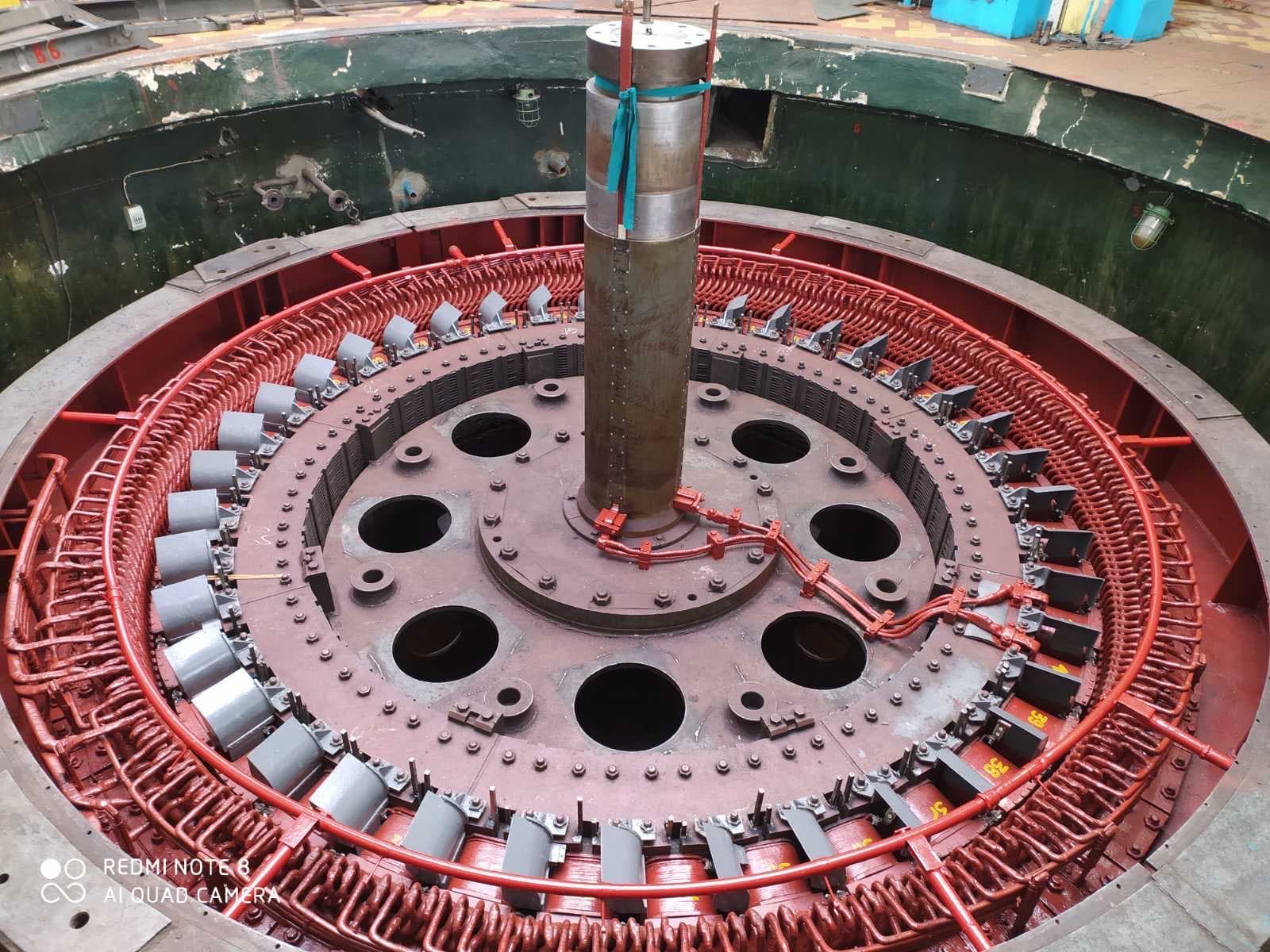
A hydrogenerator is a synchronous electrical machine that converts the mechanical energy of a hydraulic turbine into three-phase AC electrical energy.
Hydrogenerators are used at:
A hydrogenerator is part of a single hydro unit that includes:
The main design difference between a hydrogenerator and a turbogenerator lies in rotational speed and rotor construction. A hydrogenerator is usually a slow-speed, multi-pole, salient-pole machine of large diameter and relatively short axial length, in vertical or horizontal configuration. For large vertical hydrogenerators, rotor diameter can run to many meters and its mass to hundreds of tons.
IEC 60034-33:2022 sets out special requirements for large three-phase salient-pole synchronous generators and motor-generators for hydro turbines and pump-turbines. It applies to machines of 10 MVA and above, 6 kV and above, at 50 or 60 Hz, with three or more pole pairs, and supplements the general requirements of IEC 60034-1.
A hydrogenerator consists of a stationary stator and a rotating salient-pole rotor. The rotor carries poles with DC field windings that create a magnetic field. The hydraulic turbine turns the rotor — the pole field crosses the three-phase stator winding and induces an AC voltage in it.
Synchronous speed is given by:
n = 120f / p
where:
| Number of poles | Synchronous speed (50 Hz) |
|---|---|
| 10 | 600 rpm |
| 20 | 300 rpm |
| 40 | 150 rpm |
| 60 | 100 rpm |
| 80 | 75 rpm |
The lower the turbine speed, the more poles the generator must have.
The term "hydrogenerator" refers to a synchronous generator whose prime mover is a hydraulic turbine. The mechanical energy for generation comes from a water flow that has a certain head, flow rate, potential energy, and kinetic energy. The hydraulic turbine converts the water’s energy into rotating torque, and the hydrogenerator converts that torque into electrical power.
Energy conversion at a hydropower plant proceeds in sequence:
Theoretical hydraulic power of the flow is approximately:
Phydro = ρgQH
Electrical output of the unit: Pelec = ρgQHη
where ρ is water density, g is gravitational acceleration, Q is the flow rate, H is the net head, and η is the combined efficiency of the turbine, generator, and mechanical transmission. Hydro unit output therefore depends on head, flow rate, turbine and generator efficiency, hydraulic losses, and the operating mode.
The rotor poles carry a field winding fed with DC from the excitation system. The current produces a magnetic flux that passes through the rotor pole, the air gap, the stator teeth, the core back-iron, and the adjacent pole. As the rotor turns, the flux periodically shifts relative to the stator winding conductors, and EMFs offset from each other by 120 electrical degrees appear in the three phases.
Once synchronized to the grid:
| Parameter | Hydrogenerator | Turbogenerator |
|---|---|---|
| Prime mover | Hydraulic turbine | Steam or gas turbine |
| Speed | Low or medium | High |
| Number of poles | Large | Mostly 2 or 4 |
| Rotor | Salient-pole | Non-salient cylindrical |
| Diameter | Large | Comparatively small |
| Axial length | Relatively short | Long |
| Configuration | Often vertical | Mostly horizontal |
| Main support | Thrust bearing and guide bearings | Radial bearings |
| Critical factor | Geometry, magnetic symmetry, thrust bearing | High speed and rotor strength |
| Typical duty | Frequent starts, regulation, load rejection | Long base-load or cycling operation |
Hydrogenerators are classified by shaft orientation, support design, cooling method, turbine type, speed, power, duty, excitation method, rotor design, and mounting method.
The generator shaft is vertical — the most common arrangement for large and medium hydropower plants. Advantages: convenient layout above the turbine, room for a large rotor diameter, a compact powerhouse footprint, direct coupling to a vertical turbine, suitability for large ratings.
Main components: the upper and lower spiders (bridges), the thrust bearing, the upper and lower guide bearings, the shaft, rotor, stator, brake jacks, and cooling system.
IEC 63132-2:2020 provides general recommendations on procedures and tolerances for erecting vertical hydrogenerators. It emphasizes that the actual assembly sequence depends on the machine design, the powerhouse structure, and site conditions.
The shaft is horizontal. This configuration is used at small hydropower plants, run-of-river stations, with small Francis turbines, with Pelton turbines, and with bulb and some tubular units.
Advantages: simpler support design, easier bearing access, easier rotor removal, a lower powerhouse. Disadvantages: a diameter limit, a larger footprint, more difficult conditions for very large ratings, and sensitivity of a long shaft train to alignment.
In a suspended configuration, the thrust bearing sits above the rotor; the mass of the rotor, shaft, and runner is transferred through the shaft, a thrust collar or sleeve, to the thrust-bearing pads, the upper bridge, and the foundation structure. Advantages — convenient thrust-bearing access and good shaft-train stability; disadvantages — heavy loading on the upper bridge and a tall overall unit.
In an umbrella configuration, the thrust bearing sits below the rotor — the rotor effectively "covers" the thrust bearing. Variants include a design with both upper and lower guide bearings, one without an upper guide bearing, with the thrust bearing on the lower bridge, or on the turbine head cover. Advantages — a lower overall height and reduced loading on the upper structure; disadvantages — more difficult thrust-bearing access and demanding requirements for the lower support system.
Bulb units are used at low heads, high flow rates, horizontal or inclined flow, and with axial-flow turbines. The generator sits inside a sealed bulb within the water passage — limited internal space, complex cooling, demanding tightness requirements, difficult access for repair, and highly critical seals.
At a pumped-storage plant, the electrical machine operates in two modes: as a generator while producing electricity, and as a synchronous motor while pumping water to the upper reservoir. Such a machine is called a reversible motor-generator or synchronous motor-generator. It must withstand frequent starts, reversal of rotation direction, both motoring and generating modes, frequent thermal cycles, and elevated electrodynamic loads.
Modern pumped-storage plants can use variable-speed machines: a doubly-fed asynchronized motor-generator, a synchronous machine with a full-power converter, a doubly-fed machine, or a static frequency converter. Advantages: power regulation in pumping mode, optimized turbine efficiency, faster grid regulation, frequency support, and better performance under variable head.
The stator is the generator’s stationary part, consisting of a frame or housing, a core, a three-phase winding, slot wedges, a support system, end-windings, phase connections, terminals, temperature sensors, and a cooling system. A large stator is often manufactured split into several sectors for transport and assembly.
The frame carries the core mass, electromagnetic torque, short-circuit forces, vibration, thermal expansion, and reactive loads from its mounting to the foundation. It can be welded, sectional, built from several segments, and have either a flexible or rigid core mounting.
The core is built up from thin segments of electrical steel with an insulating coating to limit eddy currents, and consists of teeth, slots, the back-iron, ventilation packs, pressure plates and fingers, tie rods, and key elements. Because of its large diameter, the core is usually assembled on site at the plant.
Main assembly steps: frame inspection, installing guide and datum elements, laying up the steel segments, forming the ventilation ducts, checking joints and slot geometry, fitting pressure elements, pressing, checking pack height, density, and roundness, and testing the active steel. Assembly errors can cause local overheating, tooth vibration, loosened packs, elevated losses, and winding damage.
In sectional stators, the joints between frame and core segments deserve particular attention: possible problems — uneven magnetic reluctance, misaligned teeth, an enlarged slot gap, loosened pressing, local vibration, and heating.
A hydrogenerator’s stator winding is usually three-phase, high-voltage, two-layer, bar- or coil-type, distributed, with a short or full pitch. Large machines use form-wound bars or coils with thermosetting insulation.
A bar consists of strand copper conductors, transposition, turn and ground-wall insulation, a semiconducting slot coating, a stress-grading coating, and lead terminals — advantages: precise geometry, controlled insulation thickness, factory-testability, efficient slot fill, and suitability for high voltage. Coil windings (two slot sides joined by end-turns) are used in lower-power machines and in some older hydrogenerators.
In large-cross-section bars, the strand conductors occupy different positions relative to the slot field — without transposition, uneven induced voltages, circulating currents, stray losses, and local overheating would result. Transposition periodically changes each conductor’s position and equalizes the conditions.
The ground-wall insulation must withstand operating voltage, surge overvoltages, partial discharges, thermal cycling, vibration, electrodynamic forces, humidity, and aging. A typical modern insulation system contains mica tapes, a glass-fabric base, epoxy resin, a conductive slot coating, and a semiconducting stress-grading coating.
The conductive coating on the slot section ensures electrical contact between the insulation surface and the grounded core, equalizes potential, and prevents slot discharges. At the point where the bar exits the slot, a stress-grading coating reduces the electric-field stress in the end region — defects in these coatings can cause surface discharges, ozone, erosion, tracking, and insulation breakdown.
Slot wedges hold the winding in the slot and can be made of glass-laminate, composite, or non-magnetic materials. The wedging system can include the main wedge, packing, ripple springs, side seals, and sub-slot packing. Loosened wedges (from material shrinkage, thermal cycling, vibration, or aging) lead to bar movement, wear of the slot coating, partial discharges, and damage to the ground-wall insulation.
End-windings connect the slot sides of the winding and must withstand short-circuit electrodynamic forces, vibration, thermal expansion, twice-line-frequency electromagnetic forces, and cyclic loading. The bracing system includes support rings, spacer blocks, ties, brackets, lashings, and phase spacers.
Critical zones for phase connections and terminals include inter-coil connections, phase jumpers, neutral connections, output busbars, and cable lugs — typical defects: looseness, overheating, cracking, poor soldering, vibration fatigue, and corona discharges.
A hydrogenerator rotor usually consists of a shaft, hub, spider, rim, poles, field windings, damper winding, ventilation components, a brake disc, current leads, and slip rings or a brushless exciter. Unlike a turbogenerator’s solid-forged rotor, a hydrogenerator has separate projecting poles.
The shaft transmits torque, axial and radial loads, hydraulic disturbances, and transient torques during short circuits. It is checked for runout, straightness, journals, flanges, bolt holes, fillets, keyway joints, cracks, corrosion, and residual magnetism.
The spider transmits torque between the shaft and the rim and consists of a central hub, radial arms, a rim section, and welded or bolted joints. It must be sufficiently rigid, geometrically stable, balanced, fatigue-resistant, and capable of accommodating thermal expansion.
The rim is a massive ring structure on which the poles are fastened; it can be built from segments, stacked from laminations, assembled on keys, or shrink-fitted to the spider. Rim functions: mounting the poles, forming the magnetic path, providing flywheel effect, ensuring mechanical strength, and transmitting torque.
Each pole consists of a pole body, a pole shoe, a field winding, insulation, fastening elements, damper bars, and interpole connections. The pole shoe distributes flux, forms the air gap, affects voltage waveform, supports the damper bars, and carries centrifugal loads; its geometry affects field harmonics, reactance characteristics, torque ripple, and magnetic noise.
The field winding can be made from copper strip, profiled copper, insulated turns, or a preformed coil wound on edge, and must withstand DC current, centrifugal forces, thermal expansion, vibration, and short-term forcing. Pole-coil insulation includes interturn spacers, insulation from the pole body, end and side packing, impregnating varnishes, glass fabric, and mica materials.
Poles are fastened to the rim by T-shaped dovetails, keys, bolts, or studs and must withstand centrifugal force, electromagnetic torque, load-rejection forces, and the maximum runaway speed.
On a sudden load rejection, the turbine continues to receive energy from the water until the guide vanes fully close, and the unit’s speed rises — the maximum speed reached is called the runaway speed. The rotor and pole fastenings must have enough mechanical strength for the design maximum runaway speed.
Conductive bars in the pole shoes, joined at the ends by segments or rings, form the damper winding. It reduces rotor oscillations, damps hunting, participates in transient processes, limits harmonic effects, carries negative-sequence currents, and helps during asynchronous starting of a motor-generator in certain schemes. Damage (bar cracks, broken interpole jumpers, overheating, melted solder) reduces damping and can cause local overheating and power oscillations.
The air gap between the rotor poles and the stator is one of the key geometric parameters. It must be uniform, adequate for safe operation, minimized within design limits, and stable across all operating modes. A non-uniform gap creates an unbalanced magnetic pull, increased vibration, uneven heating, field asymmetry, and a risk of rotor-to-stator rubbing.
Causes of a non-uniform gap: stator displacement, rotor eccentricity, rim deformation, uneven pole seating, guide-bearing displacement, shaft deflection, foundation looseness, thermal deformation, or incorrect alignment.
With static eccentricity, the minimum gap stays roughly at one point of the stator; with dynamic eccentricity, the minimum gap rotates with the rotor — combined forms are also possible. Diagnostics include gap measurement, vibration and flux analysis, current measurement, geometry checks, and slow-roll rotor turning.
The thrust bearing is one of the most critical components of a vertical hydro unit. It carries the mass of the generator rotor, the shaft, the runner, the turbine’s axial hydraulic force, and dynamic axial loads. The total load can amount to hundreds or thousands of tons.
The thrust bearing can include a thrust collar, pads, a babbitt layer, support and spring elements, equalizing supports, a hydraulic leveling system, an oil bath, coolers, a jacking-oil system, and temperature, level, and vibration sensors.
Each pad forms a hydrodynamic oil wedge: as the collar rotates, it draws oil into the gap between the collar and the pad, and the film pressure carries the load without direct contact between the metal surfaces. A pad must be able to tilt slightly to form the wedge. Rigid supports, screw supports, equalizing (self-leveling) systems, spring diaphragms, spring discs, and hydraulic leveling are all used — the goal is to distribute load evenly and compensate for deformation.
At low speed, the hydrodynamic film has not yet formed, so a high-pressure jacking-oil system is used for starting, stopping, and slow rotation, feeding oil under the pads, lifting the thrust collar, reducing dry friction, and protecting the babbitt.
Thrust-bearing faults: pad overheating, uneven loading, babbitt failure, insufficient clearance, oil contamination, low viscosity, jacking-oil failure, cooling faults, collar tilt, loosened support, and oil-film cavitation.
A guide bearing holds the shaft in the radial direction. A vertical unit can have an upper generator bearing, a lower generator bearing, and a turbine guide bearing, each with its own pads or a solid liner, a babbitt layer, adjusting screws, an oil bath, seals, a cooler, and sensors. Some small or specialized units use water-lubricated bearings, polymer liners, or rubber segments, with different requirements for water quality, clearance, abrasive contamination, speed, and starting conditions.
After disconnection from the grid, a large rotor continues to coast for a long time. Mechanical brakes are used to shorten the stopping time — brake shoes or pads press against the rotor’s brake disc. The brakes can also serve as jacks for lifting the rotor, unloading the thrust bearing, maintenance, and pad adjustment.
Brake faults: uneven contact, oil contamination, worn linings, sticking, pneumatic faults, disc overheating, incomplete release, and uneven rotor lifting. A pad that has not fully released can cause heating, dust, vibration, fire, and brake-disc damage.
The rotor winding is supplied with DC. Main types: rotating (DC) excitation, brushless excitation, static thyristor excitation, and combined systems.
A traditional rotating-machine system can include a DC exciter, a pilot exciter, slip rings, a regulator, and a switching device. Disadvantages: commutator wear, brush dust, a need for regular maintenance, and slower response.
A brushless system includes an AC exciter, a rotating rectifier bridge, a pilot exciter, and an automatic voltage regulator. Advantages: no power brush contact, less maintenance, no commutator sparking, a cleaner generator zone. Disadvantages: more complex rotating-diode diagnostics, harder access to the rotor circuit, and limited ability to measure turn currents directly.
A static thyristor converter feeds the rotor through slip rings. Advantages: high speed of response, fast forcing, precise regulation, effective field suppression, and support for grid stability. Disadvantages: a brush gear, ring wear, and a need to monitor current sharing between brushes.
The automatic voltage regulator (AVR) controls field current to maintain voltage, regulate reactive power and power factor, force excitation, limit rotor and stator current, limit minimum excitation, stabilize the power system, and damp oscillations.
Hydrogenerators are mostly air-cooled. Possible systems: open ventilation, a closed air system, air-to-water heat exchangers, direct water cooling of the winding, and combined cooling.
In a closed ventilation system, air circulates inside the generator, and heated air passes through air coolers, giving up its heat to water. Advantages: less contamination, controlled temperature, limited moisture ingress, and stable conditions for the insulation.
Air coolers include tube bundles, water boxes, headers, seals, drains, and temperature sensors. Typical defects: fouling, corrosion, water leaks, clogged tubes, insufficient flow, and air locks.
A cooler water leak can reach the stator winding, the core, the rotor, the bearing systems, or the terminal insulation, causing reduced insulation resistance, corrosion, partial discharges, a ground fault, and an emergency shutdown.
Air in the rotor is moved by rotor blades, fans, radial or axial ducts, ventilation windows in the poles, and channels in the rim. Ventilation problems can stem from contamination, blocked ducts, blade damage, or incorrectly installed poles.
Apparent power: S = √3UI. Active power: P = √3UI cos φ. Reactive power: Q = √3UI sin φ.
Active power is controlled by the opening of the guide vanes, the water flow rate, the runner-blade angle (in Kaplan-type turbines), and the turbine governor mode. Reactive power is controlled by field current.
Some hydrogenerators can operate without active generation as synchronous condensers — the turbine runner is unloaded from water, for example by displacing water with compressed air or closing the guide vanes. In this mode, the machine draws a small amount of active power, generates or absorbs reactive power, supports voltage, adds grid inertia, and provides short-circuit power.
ISO 20816-5 separately addresses vibration in hydro units and motor-generators, but does not extend its typical criteria to every synchronous-condenser mode, so such modes require criteria agreed between the manufacturer and the owner.
The generator experiences loads that originate in the turbine: pressure pulsations, hydraulic imbalance, cavitation, vortex ropes, unstable guide-vane operation, uneven flow, axial and radial forces, and water hammer. Generator vibration does not always have an electrical or mechanical cause — its source can lie in the turbine’s flow path.
Cavitation occurs when local water pressure drops to the vapor pressure: vapor bubbles form and collapse in a higher-pressure zone, causing erosion, noise, vibration, reduced efficiency, and torque pulsations. These oscillations are transmitted through the shaft to the generator and can affect the bearings, fastenings, air gap, and stator vibration.
In Francis turbines operating away from the best efficiency point, an unstable vortex structure (a vortex rope) can form in the draft-tube cone, creating low-frequency pressure pulsations, power oscillations, shaft vibration, and unit instability.
Modern hydropower plants often run in a cycling regime to balance the grid. Frequent starts create thermal cycling of the stator and rotor, cyclic forces in the end-windings, brake wear, thrust-bearing loading, mechanical fatigue of joints, changes in rim tension, and insulation aging. The number of starts should be factored into life assessment just as operating hours are.
On a sudden disconnection from the grid, electromagnetic torque vanishes abruptly, the turbine continues to receive water energy, speed begins to rise, the governor closes the guide vanes, and the unit goes through a transient — possible consequences: acceleration to elevated speed, axial and radial oscillations, water hammer, and loading on the poles and rim.
Negative-sequence current from unbalanced loading creates a field that, relative to the rotor, rotates at high relative speed and induces currents in the damper bars, pole shoes, rim, and fastenings, causing overheating, cracking, and damage to the damper system.
On loss of excitation, the generator can absorb reactive power, lose synchronism, shift into an asynchronous mode, overheat the rotor, and overload the damper winding. Causes: an open rotor circuit, converter failure, brush failure, an open interpole connection, damaged rotating diodes, or an AVR error.
If water inflow or turbine torque is insufficient but the generator stays connected to the grid, it can shift into motoring mode — the grid begins to drive the unit. This is acceptable briefly in some regimes, but uncontrolled motoring can lead to turbine damage, overheating, a hazardous hydraulic condition, and cavitation.
Insulation aging, slot and surface partial discharges, loosened wedges, bar movement, end-winding damage, loosened phase connections, interturn and phase-to-phase faults, ground faults, local overheating, contamination, and moisture ingress — these can occur in internal insulation voids, between layers, at the copper-to-insulation interface, in the slot clearance, or on the end-winding surface. Signs: white powder, ozone, a characteristic smell, surface erosion, blackening, and tracking.
Typical core defects: interlaminar shorts, loosened pressing, pack vibration, tooth damage, rotor-rub marks, melting, corrosion, and damaged pressure fingers. An interlaminar short creates an eddy-current loop and can cause intense local heating.
A pole-coil interturn fault, a coil-to-pole-body short, an open interpole connection, pole looseness, damaged fastening keys, rim deformation, loosened rim joints, a spider crack, pole displacement, damper-bar damage, and clogged ventilation ducts.
A pole-coil interturn fault reduces the pole’s magnetomotive force, creates magnetic-field asymmetry, uneven heating, increased vibration, and a change in field current.
A single rotor-circuit ground fault does not always produce a large current, but a second fault at another point can short-circuit part of the poles or turns and cause severe magnetic asymmetry, local overheating, vibration, and arc damage.
Pole looseness (from insufficient tightening, worn keys, fretting, rim deformation, or frequent runaway events) shows up as metal dust, a change in gap, increased vibration, noise, and local heating.
The rim can lose roundness because of loosened joints, thermal cycling, insufficient tension, pack displacement, or runaway events — consequences: a non-uniform air gap, vibration, pole displacement, imbalance, unbalanced magnetic pull, and a rubbing risk.
Critical zones for spider cracks: welds, arm transitions, the hub area, rim-fastening points, and stress concentrations; causes — fatigue, thermal cycling, vibration, welding defects, fault torques, and runaway events.
Sources of hydrogenerator vibration can be mechanical, electromagnetic, hydraulic, structural, or thermal. Typical causes: imbalance, misalignment, a non-uniform air gap, rim deformation, pole displacement, a bearing defect, hydraulic imbalance, cavitation, a vortex rope, stator looseness, resonance, a shorted pole, and a spider crack.
The magnetic field produces radial forces on the core teeth and back-iron — the main vibration components can be related to twice grid frequency, slot harmonics, the number of poles, a non-uniform gap, and magnetic asymmetry.
Shaft voltages (from magnetic asymmetry, a non-uniform gap, residual magnetism, pole asymmetry, or static charge) can drive current through a bearing, causing pitting, babbitt burning, surface damage, and oil-film breakdown. Bearing insulation, a shaft grounding brush, and shaft-voltage monitoring are used to limit the current.
Comprehensive diagnostics covers operating-history analysis, visual inspection, electrical testing, core diagnostics, slot-wedge inspection, partial-discharge measurement, rotor diagnostics, pole inspection, air-gap monitoring, vibration analysis, thrust-bearing inspection, oil analysis, cooling checks, excitation-system checks, and functional protection testing.
Gather operating hours, number of starts, number of load rejections, runaway events, unbalanced operation, overloads, peak temperatures, vibration trends, air-gap data, partial-discharge history, thrust-bearing condition, pole repairs, and prior core defects.
For the stator, check cleanliness, humidity, signs of water, slot wedges, bar surfaces, corona protection, end-windings, phase connections, the core, and air coolers. For the rotor — pole coils, insulation, interpole connections, pole fastenings, damper bars, the rim, rim joints, the spider, welds, balancing weights, and slip rings.
Insulation resistance is measured for the stator winding to ground, individual phases, the rotor winding, the excitation system, and bearing insulation, accounting for temperature, humidity, and prior results. The polarization index helps assess contamination, moisture, and absorption behavior, though a high value alone does not rule out a local defect.
DC resistance is measured for the stator phase windings, pole coils, rotor circuits, and interpole connections, comparing phases and poles with each other and with nameplate values — a deviation can indicate poor contact, an open circuit, shorted turns, or a soldering defect.
A hipot test confirms the dielectric strength of the insulation (power-frequency AC, resonant testing, or DC per the applicable procedures). Tan δ measurement helps assess the condition of the ground-wall insulation, delamination, moisture, contamination, and voids.
Partial discharge is diagnosed offline, online, periodically, or continuously, evaluating amplitude, phase-resolved pattern, pulse shape, polarity, dependence on active and reactive power, and trend. A single numeric level is not enough to draw a conclusion about winding condition.
Slot wedges are checked by tapping, mechanical assessment, automated mapping, electromagnetic systems, and displacement measurement. The core is diagnosed by ring-flux magnetization, thermal imaging, low-flux electromagnetic testing, EL CID or similar methods, and local measurement.
In a ring-flux test, a temporary winding creates flux in the core while temperature is monitored — a local hot spot can indicate an interlaminar short. The air gap is measured stationary, during slow rotation, and under different thermal states, analyzing average, minimum, and maximum values, ovality, and change with rotation, load, and temperature.
Pole coils are checked with resistance and voltage-drop measurement, surge testing, a ground test, thermal imaging, and interturn-insulation monitoring. A test current is passed through the series chain of poles and the voltage drop across each coil is measured — a deviation can indicate shorted turns, poor contact, or an interpole-connection defect.
In a pole-coil surge test, the coils’ response to a pulse signal is compared — a shorted turn changes inductance, damping, oscillation frequency, and pulse shape. The damper winding is checked by visual inspection, dye-penetrant testing, resistance measurement, ultrasonic joint testing, and thermal imaging.
Nondestructive rotor testing can include ultrasonic shaft testing, magnetic-particle and dye-penetrant testing, ultrasonic weld testing, bolt inspection, pole-dovetail inspection, rim inspection, and spider inspection.
Monitored parameters include bearing vibration, shaft displacement, orbit, phase, spectrum, axial position, gap pulsations, core and spider vibration, and dependence on load and excitation.
ISO 20816-5:2018 applies to vibration assessment for many hydro units with hydraulic turbines, pump-turbines, and motor-generators, but specific criteria must account for the unit’s design and measurement conditions.
Two mutually perpendicular displacement probes allow the shaft-center orbit to be plotted — the orbit shape helps identify imbalance, misalignment, rubbing, oil-film instability, and hydraulic disturbance. During run-up and coastdown, speed, amplitude, phase, orbit, gap, bearing temperature, the moment excitation is applied, and the moment of synchronization are all recorded — this helps separate mechanical defects, electromagnetic effects, hydraulic disturbances, and structural resonances.
Thrust-bearing monitoring covers each pad’s temperature, oil temperature and level, jacking-system pressure, babbitt condition, oil-film thickness, axial position, pad loading, and oil analysis (viscosity, acid number, water content, particulate contamination, wear debris) — babbitt, steel, or bronze in a sample can indicate bearing damage.
Thermal imaging is used to check phase connections, slip rings, brushes, pole coils, bearings, coolers, current leads, and excitation-system connections — temperatures must be compared under the same load and similar cooling conditions.
A runaway condition (overspeed) can be caused by load rejection, a guide-vane fault, governor failure, a control error, or servomotor jamming. Protection can include an electrical speed sensor, a mechanical device, an independent backup channel, emergency turbine shutdown, and an emergency gate.
Thrust-bearing protection monitors pad temperature, oil temperature and level, pressure, cooling-water flow, pump operation, and jacking-oil pressure. Overheating of a single pad can develop rapidly, so monitoring each support zone individually — not just the average oil temperature — is important.
The scope of a planned repair depends on power, design, operating hours, number of starts, the hydropower or pumped-storage regime, insulation condition, vibration-monitoring results, thrust-bearing and rotor condition, manufacturer recommendations, and defect history. Repair can range from no rotor removal, to lifting the rotor, to full rotor disassembly, pole removal, replacing individual coils, rewinding the stator, or reconstructing the core, rim, or spider.
A large vertical rotor is lifted with an overhead crane. Before lifting, disconnect the current leads and shaft, verify the center of gravity, fit a lifting beam, check the crane’s capacity, and ensure a synchronized lift, avoiding tilting, pole-to-core impact, insulation loading, or contact with end-windings.
Poles are often removed to repair the stator winding, check fastenings, repair coils, reduce rotor mass, balance, or reconstruct the rim. Before removal, record the pole number, position, polarity, coil resistance, gaps, balancing weights, and fastening condition — poles must never be rearranged arbitrarily without re-checking magnetic and mechanical symmetry.
Core repair can include cleaning, tightening the pressing, repairing pressure fingers, separating shorted laminations, restoring interlaminar insulation, tooth repair, fitting local inserts, repacking a section, or a full core replacement. Electromagnetic testing is repeated after the repair.
Stator winding repair can include cleaning, drying, restoring the slot and stress-grading coatings, re-wedging, bracing repair, phase-connection repair, local insulation restoration, replacing a coil, bar, or group of coils, or a full rewind.
Bar or coil replacement: marking, removing the bracing, unsoldering or disconnecting, removing the slot wedges, extracting the element, inspecting the slot, repairing the core, checking the new element, inserting it, restoring wedging, making connections, restoring corona protection, re-bracing the end-windings, and electrical testing.
A complete stator rewind is required for systemic aging, numerous defects, an emergency failure, insufficient remaining insulation life, a power upgrade, or a voltage increase. Reconstruction can also modernize the insulation system, transposition, slot geometry, winding scheme, end-winding bracing, wedging system, and corona protection.
Pole-coil repair can include cleaning, drying, restoring interturn insulation, repairing leads, re-soldering connections, restoring clamping elements, replacing packing, rewinding the coil, impregnation, forming, and electrical testing.
Manufacturing a new pole coil: measuring the old coil, determining the copper grade and cross-section, recording the turn count, making a form, winding, laying up interturn insulation, forming the geometry, pressing, impregnation or baking, machining, dimensional checks, resistance measurement, interturn-insulation testing, and a ground test. The new coil must match the other poles in turn count, resistance, mass, geometry, and thermal characteristics.
Rim repair can include tightening tie rods, joint repair, replacing damaged segments, restoring roundness and tension, correcting looseness, and balancing. Changing rim tension must be based on a calculation and the manufacturer’s documentation.
Spider repair can include weld inspection, crack removal, repair welding, heat treatment, reinforcement, replacing elements, and checking geometry and stiffness. Repairing a welded spider without an engineering analysis can change the stress distribution, stiffness, natural frequencies, and structural life.
Damper-system repair can include replacing bars, restoring solder joints, replacing interpole jumpers, repairing short-circuiting segments, and checking resistance and cracks.
Thrust-bearing repair can include removing pads, inspecting the babbitt, dye-penetrant and ultrasonic bond testing, re-babbitting, machining, scraping, adjusting the supports, restoring oil channels, and repairing the jacking system.
Re-babbitting: removing the old babbitt, cleaning the base, checking for cracks, surface preparation, tinning, pouring the new alloy, checking the bond, machining, forming oil grooves, scraping, checking geometry, and nondestructive testing.
Alignment covers more than matching geometric axes — the stator axis, rotor axis, guide-bearing axis, thrust-bearing axis, turbine axis, runner position, seal positions, air gap, and hydraulic clearances must all be reconciled.
General recommendations on erection procedures and tolerances for hydro-electric machines are given in IEC 63132-1:2020, with a separate standard for vertical generators in IEC 63132-2:2020. Actual tolerances must be determined from the documentation of the specific unit.
Shaft verticality is measured using mechanical wires, laser systems, precision levels, indicators, and optical instruments, checking position at different rotation angles, flange runout, journal displacement, tilt, and orbit shape during slow rotation.
Rotor imbalance can be caused by unequal pole or coil mass, pole rearrangement, repair welding, rim changes, missing weights, or deformation. Balancing can include static balancing, low-speed balancing, balancing at operating speed, trial weights, and vector analysis of amplitude and phase.
The test package can include insulation resistance, polarization index, phase and pole DC resistance, tan δ, partial discharge, hipot and surge testing, core inspection, slot-wedge and air-gap control, pole and damper-system checks, bearing-insulation control, checks of the excitation system, brakes, jacking oil, and the thrust bearing, cooling checks, functional protection testing, start-up testing, vibration analysis, and a load test.
Before the first start-up, verify that installation is complete, there are no foreign objects, gaps and pole/stator fastenings are correct, insulation resistance and grounding are sound, the oil system, jacking oil, cooling, brakes, guide bearings, thrust bearing, excitation, protection, turbine governor, emergency gates, synchronizing system, direction of rotation, and vibration-monitoring channels are all in order.
During start-up, monitor jacking-oil pressure, the moment the collar lifts off, brake operation, pad and guide-bearing temperature, vibration, axial position, air gap, field current, voltage, frequency, run-up, governor operation, synchronization, and how parameters change with load.
What not to do:
| Symptom | Possible cause | What to check |
|---|---|---|
| High vibration with no excitation | Imbalance | Pole mass, balancing |
| Vibration rises after excitation | Magnetic asymmetry | Pole coils, gap |
| High vibration at a specific load | Hydraulic condition | The turbine, pressure pulsations |
| Non-uniform air gap | Eccentricity | Stator, rotor, bearings |
| One pole runs hot | Interturn fault | Resistance and voltage drop |
| Rotor ground protection trips | Insulation damage | Poles and current leads |
| White dust in the slot | Bar movement | Wedges and slot coating |
| Ozone | Partial discharge | Corona protection |
| A phase connection heats up | Poor contact | Resistance and thermal imaging |
| Local core heating | Interlaminar short | EL CID or ring test |
| Thrust-bearing pad overheats | Uneven loading | Support, oil, collar |
| Water in the oil | Cooler leak | Heat exchanger |
| Currents through a bearing | Broken insulation | Grounding and insulation |
| Metallic noise | Pole looseness | Fastenings |
| Vibration on load rejection | Overspeed or water hammer | Governor and turbine |
| High stator temperature | Overload or ventilation | Current and cooling |
| Unequal phase resistances | Poor connection | Phase contacts |
| Unstable voltage | AVR or excitation issue | Regulator and power circuit |
| Slow stopping | Brake fault | Pneumatics and pads |
| Brake-disc heating | Incomplete release | Shoe position |
Possible causes: poles installed in the wrong positions, balancing weights changed, a coil with a different mass, the rotor mounted with eccentricity, a displaced guide bearing, or altered rim geometry. Check amplitude, phase, air gap, pole mass, weight position, alignment, and the shaft orbit.
Likely causes: shorted pole turns, an incorrect turn count, reversed pole polarity, an uneven gap, an interpole-connection defect, or magnetic core asymmetry.
Possible causes: uneven loading, incorrect support adjustment, a clogged oil channel, a babbitt defect, thrust-collar deformation, or insufficient oil supply. It is unacceptable to judge condition from average oil temperature alone.
Check bar-fit tightness, slot-coating damage, contact with the core, the stress-grading zone, cleanliness, the wrong packing materials, and grounding of the measuring system.
Possible causes: pole displacement, rim deformation, loosened fastening, guide-bearing displacement, or mechanical rotor deformation. A full geometric check is needed before the next start.
A synchronous generator driven by a hydraulic turbine.
Because hydro turbines rotate much slower than steam turbines, while the electrical frequency must stay at 50 or 60 Hz.
A large diameter allows fitting many poles and generating the required torque at low speed.
A bearing that carries the mass of the rotating parts and the turbine’s axial force.
To create an oil film at low speed, before the hydrodynamic wedge has formed.
The maximum speed the unit can reach after a load rejection, before the turbine shuts off.
It damps oscillations and carries induced currents during transient and unbalanced conditions.
A non-uniform gap creates an unbalanced magnetic pull, vibration, and a rubbing risk.
They can differ in mass, position, packing, and balancing — they can only be swapped after re-verification.
An umbrella design has the thrust bearing below the rotor; a suspended design has it above the rotor.
Yes. Cavitation, vortex ropes, and pressure pulsations are transmitted through the shaft and foundation.
No. Partial discharge, tan δ, and testing of the core, rotor, gap, bearings, and vibration are all required.
Even a small mass difference at a large radius creates significant imbalance.
Operation without significant active power, used to generate or absorb reactive power.
Electropromremont LLC performs diagnostics, repair, restoration, and manufacturing of components for synchronous generators and hydrogenerators, within its own process capabilities, technical documentation, and an agreed scope of work.
The scope of work can include:
The repair scope for a specific hydrogenerator is determined after analyzing the unit type, power, design, shaft orientation, dimensions, rotor mass, mounting method, technical documentation, the nature of the damage, and the requirements of the manufacturer and the customer.
A hydrogenerator is a large, slow-speed synchronous machine that operates in close interdependence with the hydraulic turbine, the shaft train, the thrust bearing, the guide bearings, and the governing system.
Key features of a hydrogenerator:
A hydrogenerator’s technical condition cannot be assessed from a single electrical or vibration parameter. Its electrical, magnetic, mechanical, thermal, hydraulic, and geometric characteristics must be analyzed together.
A proper repair should include:
This article is for general informational purposes and is not an operating, erection, or repair manual for any specific hydrogenerator. The technology for disassembly, rotor lifting, pole removal, winding repair, thrust-bearing adjustment, alignment, balancing, and testing must be determined based on the manufacturer’s documentation, drawings, the unit’s record card, defect-inspection results, applicable standards, hydropower- or pumped-storage-plant instructions, calculations, and industrial-safety requirements.
Particular hazards include high voltage, the large mass of the rotor, significant axial loading, the stored energy of the rotating parts, water pressure, pressurized oil, lifting equipment, the braking system, jacking the rotor, running the unit up to runaway speed, and hipot testing.
Without a specialized organization, qualified personnel, and an approved procedure, it is not permitted to lift the rotor, remove poles, change rim tension, repair the spider, adjust the thrust bearing, relocate guide bearings, change the air gap, repair the high-voltage winding, perform high-voltage or runaway testing, or start the unit after a repair.
The actual scope and permissibility of work by Electropromremont LLC on a specific hydrogenerator are determined after receiving technical documentation and data on its design, power, dimensions, mass, damage, and testing requirements.
This material is for informational purposes. The values, diagnostic methods, scope of work and recommendations given here are general and do not replace the manufacturer’s technical documentation. The final decision for a specific machine is made from its own diagnostics and inspection, taking into account its type, power, design, duty, operating history and applicable standards.
We handle stator, rotor and thrust-bearing defect inspection, electrical and nondestructive testing, pole-coil, rim and spider repair, balancing, alignment, and a controlled start-up matched to your machine’s design.