How are synchronous rotors rewound?
  1. // ELEKTROPROMREMONT
  2. Rotor rewinding

How are synchronous rotors rewound?

Rewinding a synchronous rotor is a comprehensive restoration of the field winding, its insulation, the interpole connections, the leads, the slip rings, the mechanical fastenings and the rotor’s balance. This kind of repair differs substantially from rewinding a wound rotor in an induction motor.

In a synchronous machine, the rotor creates the main magnetic field, and its winding is fed DC current through slip rings, a static excitation system, or a brushless exciter with a rotating rectifier. The condition of the rotor winding governs the machine’s magnetic field, generator voltage, reactive power, synchronous stability, and reliable motor starting.

An error in turn count, in one pole’s polarity, in conductor cross-section, or in coil fastening can cause magnetic asymmetry, heavy vibration, local overheating, loss of synchronism, or the rotor touching the stator in an emergency. Rewinding therefore cannot be reduced to swapping old wire for new — the electromagnetic parameters, dielectric strength, mechanical fastening and dynamic balance all need restoring together.
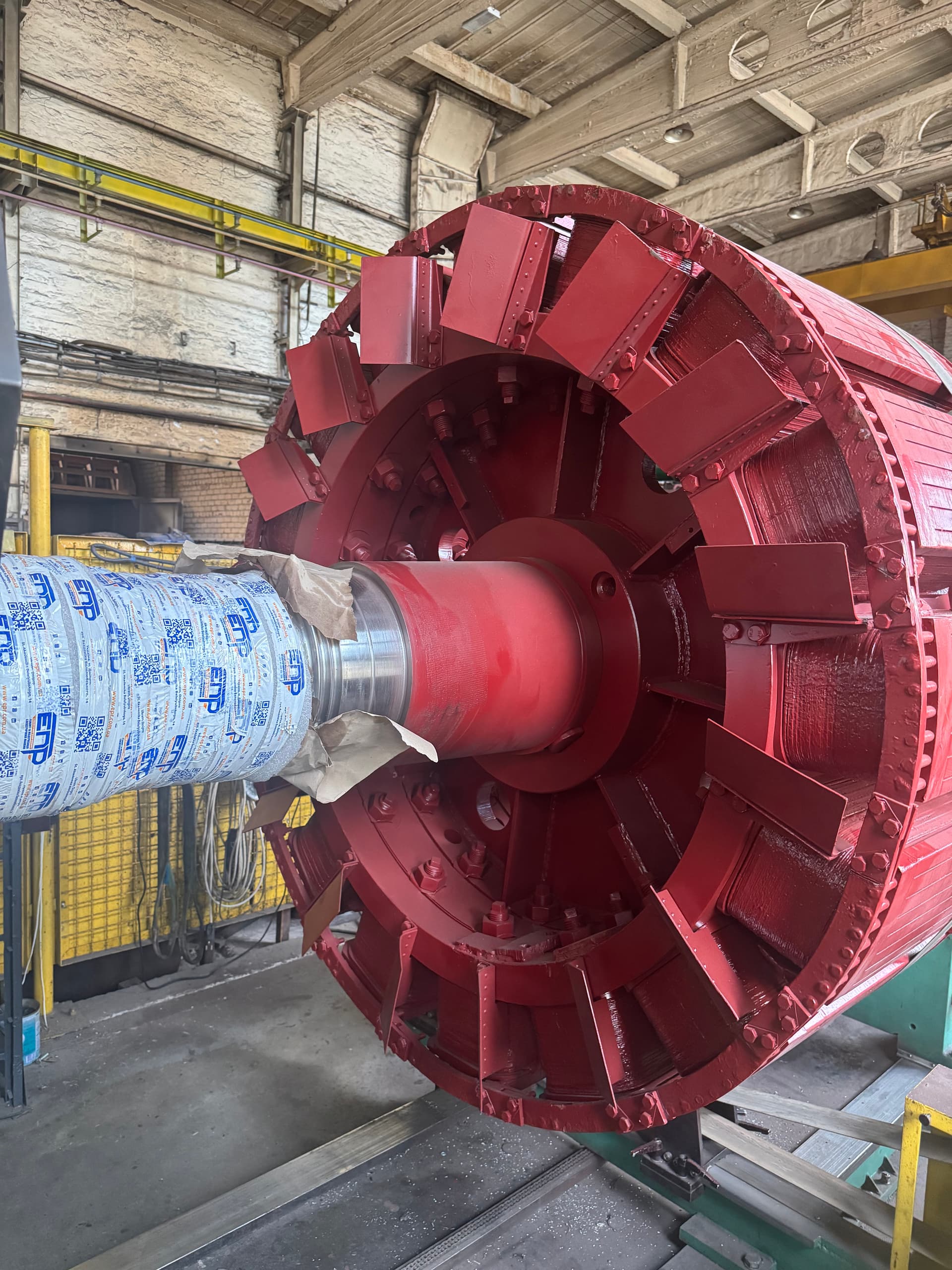
Salient-pole and non-salient-pole rotors

A salient-pole rotor consists of individual poles that clearly project from its surface — each carries a pole core, a pole shoe, a field coil, an insulating frame, and elements of the damper cage. Such rotors are typical of hydro generators, synchronous motors, and low- to medium-speed machines.

A non-salient-pole (cylindrical) rotor has an almost cylindrical surface, with the field winding set into slots in a massive forged body, held by slot wedges and end retaining rings. These rotors are used in turbogenerators and high-speed synchronous machines — their repair is considerably harder, given the high rotational speed, the large centrifugal forces, and how critical any change in mass distribution becomes. Salient-pole repair methods cannot be applied directly to a turbogenerator rotor.

When rewinding is needed, and when local repair will do

Rewinding may be necessary for an interturn short, a coil breakdown to the pole core or to the shaft, a broken conductor or interpole connection, general or local overheating of a pole, coil deformation, loosened mechanical fastening, or aging across the whole insulation system.

Local repair is possible when the defect is accessible, the damage is limited to a single joint or lead, the rest of the coil’s insulation still has service life left, and the coil itself is not deformed — for example, replacing a flexible interpole connection, restoring a soldered joint, or repairing a coil’s fastening. An interturn defect inside a multi-layer coil is not usually fixed by surface repair alone.

A full rewind can be impractical when the shaft has an unrepairable crack, pole fastening is badly damaged, the forging of a non-salient-pole rotor has a critical flaw, the strength of the retaining rings cannot be confirmed, or reliable winding data is simply unavailable.

Analyzing the cause of the failure

Before repair, find out whether there was an overload of field current, prolonged forcing, incorrect voltage-regulator operation, an out-of-step condition, loss of excitation, a ground fault, elevated vibration, overheated slip rings, faulty rotating-rectifier diodes, or damper-cage damage. Without removing the cause, a new winding can fail again.

The pattern of damage often hints at the cause: uniform darkening across all coils points to prolonged excessive field current or inadequate ventilation; overheating of a single pole points to an interturn short, a weak joint, or a wrong turn count; a burnt interpole connection points to high contact resistance or a vibration-induced crack.

Incoming tests and checking the excitation system

If the winding’s condition allows, insulation resistance, the winding’s and each pole’s resistance, interturn condition, a surge-test comparison of the coils, and the voltage drop across each pole are all measured. Overall winding resistance can stay nearly normal even with an interturn short in a few turns or a weak joint — so individual poles must be compared, not just the overall resistance.

Before deciding to rewind, the excitation source itself is checked: for a brush-type system — the slip rings, brushes, rocker and regulator; for a brushless system — the exciter’s winding, the rotating diodes, the varistors and the pilot exciter. A faulty diode can produce a pulsating or asymmetric current that overheats the rotor winding.

Mechanical inspection

Rewinding must not begin before the rotor’s mechanical soundness is confirmed — the shaft, pole fastening, pole wedges, bands, damper cage, slip rings, rotating rectifier, and balance weights are all checked. A loose pole can change the air gap, cause vibration, damage the coil, or even lead to the pole coming loose in service — so bolt and fastener torque is checked against the documentation, with magnetic-particle, dye-penetrant or ultrasonic testing applied as needed.

The end retaining rings of a non-salient-pole rotor hold the winding’s end turns against large centrifugal forces, so a defect there can be catastrophic — cracks, corrosion, stress-corrosion damage, and the state of the fit are checked with specialized methods.

Recording the winding data

Before disassembly, record the number of poles and coils, the turn count of each coil, conductor size, winding direction, the polarity sequence, the interpole connection scheme, the resistance and mass of each coil, and the insulation type and thickness. Each pole’s polarity must be recorded individually — poles must alternate north-south, and if one coil is connected the wrong way round, magnetic asymmetry, vibration and higher field current result, none of which a correct overall winding resistance would reveal.

The old winding may have been repaired incorrectly or partly replaced before, so the recorded data is compared against the nameplate, drawings, rated field current and voltage, and data from a comparable machine.

Disassembly and checking the pole core

Disassembling a salient-pole rotor involves disconnecting the interpole connections and main leads, then carefully lifting the coil off the pole core without uncontrolled force that could deform the pole or damage the damper cage. Disassembling a non-salient-pole winding is harder — it involves removing the end retaining rings, wedges, and sub-slot elements, since the retaining rings can carry significant preload and are critical to the rotor’s safety.

After cleaning, a salient-pole core is checked for the state of the laminated stack, shifted laminations, signs of overheating, and coil fit. A damaged core can damage new insulation, cause local heating, or produce pole asymmetry — so the geometry, air gap, and magnetic response of every pole are compared.

Checking the damper winding

The damper cage consists of bars in the pole shoes, short-circuiting segments, and connecting arcs — it damps rotor oscillations, reduces torque pulsations, and assists the starting of a synchronous motor. Typical defects include cracked or broken bars, loosening in the slots, or arc traces; a faulty damper cage can cause elevated vibration, hot pole shoes, and an unstable start.

The insulation system and coil manufacturing

The insulation system includes turn insulation on the conductor, ground-wall insulation on the coil, the insulating frame, insulation of the interpole connections, and the impregnating resin. The materials must withstand not just the steady field voltage but transient overvoltages from forcing, an emergency field discharge, or a rectifier fault — so turn insulation needs impulse withstand, not just its rated dielectric strength.

Salient-pole coils are wound from round or rectangular wire on a form that accounts for the pole core’s size, insulation thickness, and shrinkage during processing — the outer dimensions of an old, overheated coil should never be used as the reference, since it may have deformed. Turn count is checked with a winding-machine counter, by measuring resistance, and by comparing mass — no secondary method should ever fully replace a direct count, and a mass difference between otherwise identical coils adds imbalance.

Fitting the coils and the interpole connections

A coil is fitted onto its pole under controlled force, without impacts — driving it on can damage the ground-wall insulation, create a hidden crack, or deform the turns, and the damage may only show up after several thermal cycles. Fastening must hold the coil in place while still allowing thermal expansion: fully blocking thermal movement can build up high internal stresses and crack the insulation.

Interpole connections are made by soldering, welding, crimping, or bolted contacts, aiming for low contact resistance and vibration resistance. A joint must never carry mechanical load — it is supported by separate brackets or flexible elements, since vibration can otherwise fatigue the copper, loosen a bolt, or break down the insulation. Before impregnation, the polarity of every pole must be checked electrically or magnetically — one wrongly connected pole distorts the resultant field and causes torque pulsation, vibration, and generator instability.

Impregnation, curing and final tests

Impregnation binds the turns together, fills voids, raises dielectric strength, and reduces vibration — dip, vacuum, or vacuum-pressure impregnation is used depending on the rotor’s design. Even distribution of the impregnating material matters for the rotor: resin building up on one side can create imbalance or block ventilation, so more material does not mean better insulation.

After cooling, final tests measure insulation resistance, each coil’s resistance, interturn condition, a surge-test comparison, and a high-voltage withstand test against the pole core and the shaft. An excessive test can damage new insulation or accelerate aging, so the test voltage is chosen from the rated field voltage, the design, and the manufacturer’s documentation — never arbitrarily.

Slip rings and the rotating rectifier

For a brush-type machine, check the ring diameter, ovality, radial and face run-out, burning, and the insulation between rings — excess run-out causes the brushes to bounce, spark, and produce an unstable field current, so even a correctly rewound rotor can run unstably because of a slip-ring defect.

For a brushless machine, after repair check the diodes, varistors, heat sinks, and the rotating rectifier’s mechanical fastening. Replacing one diode with a different type without checking its current, reverse voltage, and mechanical design can be unacceptable, and uneven replacement of rectifier parts shifts the balance — so after major rectifier work, the rotor must be re-checked on the balancing machine.

Checking run-out and dynamic balancing

After the repair is complete, check the run-out of the bearing journals, the coupling seat, the slip rings and the poles — a rotor with uncorrected excessive run-out should never be balanced. Rewinding changes mass distribution through the new coils, insulation, interpole connections, bands, and impregnating material, so the rotor must always be checked dynamically, even when the new coils’ mass is nominally the same — imbalance depends on the distance from the axis and the angular position, not mass alone.

Diagnostic table

SignLikely causeWhat to check
Uniform darkening across all coilsProlonged excess field current, poor ventilationForcing regime, cooling
One pole overheatsAn interturn short, a weak jointVoltage drop across the poles
A burnt interpole connectionHigh contact resistance, a vibration crackThe joint, bolt torque
Unstable field currentA faulty rotating-rectifier diodeDiodes, varistors
Sparking on the slip ringsRing run-out, contaminationRing geometry, brushes
Vibration after rewindingA shift in mass distributionDynamic balancing
Loss of synchronismPole asymmetry, a damper-cage defectPolarity, damper bars

Common rewinding mistakes

  • disassembling without recording the winding data and each pole’s polarity;
  • copying the outer dimensions of a deformed old coil;
  • skipping inspection of the pole core and the damper cage;
  • fastening a coil rigidly without allowing for thermal expansion;
  • uneven impregnation that creates imbalance;
  • not checking polarity before impregnation;
  • replacing a rotating-rectifier diode without checking its ratings;
  • skipping dynamic balancing after the repair.

Frequently asked questions

How does rewinding a synchronous rotor differ from rewinding a wound rotor in an induction motor?

A synchronous rotor creates the machine’s main magnetic field and runs on DC field current, so pole polarity, the damper cage, the slip rings, and the rotating rectifier are all critical — none of which an induction motor’s wound rotor has.

Can just one coil of a salient-pole rotor be replaced?

In many designs, yes, if the rest of the winding is sound — but polarity and resistance must be checked afterward, and the rotor dynamically balanced.

Does overall winding resistance always reveal an interturn short?

No. Overall resistance can stay nearly normal, so individual poles must be compared using the voltage-drop method, inductance, or a surge test.

Why does the rotating rectifier need checking after a repair?

A faulty diode produces a pulsating or asymmetric field current that overheats the winding, and uneven replacement of rectifier components shifts the rotor’s balance.

Does the rotor need balancing after rewinding?

Yes, almost always — the new coils, insulation, connections, and impregnating material change mass distribution even when the coils’ nominal mass is identical.

Can a turbogenerator rotor be rewound the same way as a salient-pole one?

No. A non-salient-pole rotor requires disassembling the slot system and the end retaining rings, which are critical to mechanical safety at high speed.

Synchronous rotor rewinding

EPR (Elektropromremont) diagnoses, repairs and rewinds salient-pole and non-salient-pole rotors in synchronous motors and generators.

The scope of work includes:

  • inspecting the field winding, the pole core and the damper cage;
  • manufacturing new field coils and insulation parts;
  • restoring interpole connections and main leads;
  • repairing or replacing slip rings and the rotating rectifier;
  • vacuum and vacuum-pressure impregnation;
  • checking run-out and dynamically balancing the rotor;
  • final electrical testing and testing the excitation system.

Important disclaimer

This material is for informational purposes. The values, diagnostic methods, scope of work and recommendations given here are general and do not replace the manufacturer’s technical documentation. The final decision for a specific machine is made from its own diagnostics and inspection, taking into account its type, power, design, duty, operating history and applicable standards.

Need a rotor rewind?

We carry out inspection, field-winding rewinding, slip-ring or rotating-rectifier repair, and dynamic rotor balancing.

Get a consultation