Can a stator be checked with an ordinary multimeter?
It can reveal an open circuit and a gross inequality of resistances. It is impossible to fully assess the condition of the insulation, the interturn strength and the core with a multimeter.
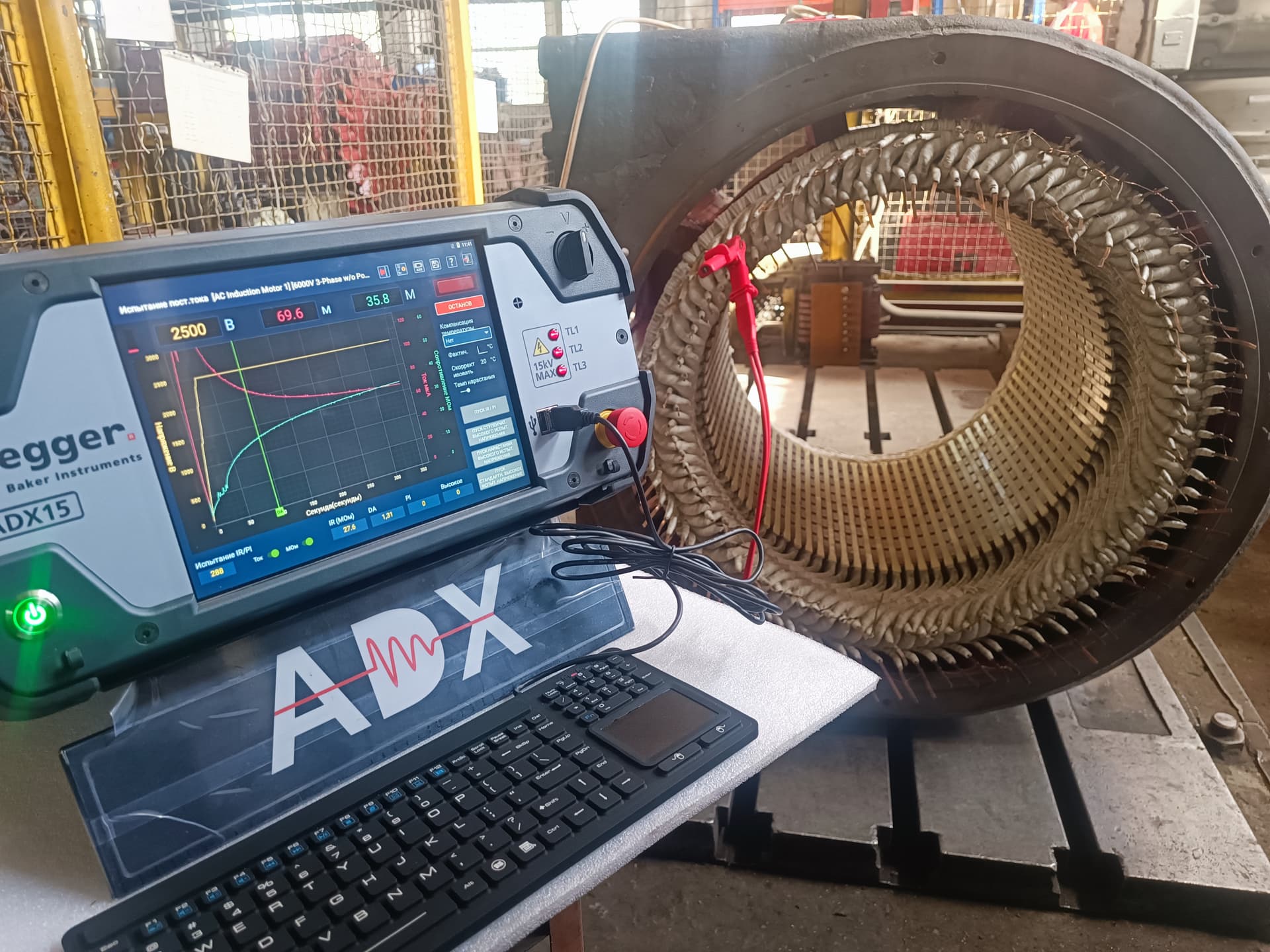
Testing the stator is one of the core operations during the diagnostics, maintenance and repair of an electric motor. The reliability, temperature, output and service life of an electrical machine depend directly on the condition of the winding, the slot insulation, the core, the connections and the stator mounting.
A stator fault does not always show up as a complete short circuit or a protection trip.
At an early stage the motor can keep running while it:
A complete stator check should therefore not be limited to a megohmmeter measurement of insulation resistance. A megohmmeter can reveal a breakdown or a general deterioration of the insulation to the frame, but it often fails to show:
Reliable diagnostics must combine visual inspection, electrical measurements, special tests and an analysis of the motor’s operating history.
To test the stator of an electric motor, the following steps should be carried out in sequence:
The final scope of testing depends on the voltage, power and design of the motor, its condition, and the reasons it was taken out of service.
The stator of an electric motor is not just a winding.
Its main elements include:
A defect in any of these elements can damage the winding.
A full or partial stator check is carried out:
Diagnostics should allow the following to be found or ruled out:
Depending on the scope of diagnostics, the following are used:
Not every check can be safely carried out on site at the plant. Surge and high-voltage tests must be performed by trained personnel using suitable equipment.
Before testing begins, the following must be recorded:
Comparison with previous results is often more valuable than the assessment of a single measurement.
It is necessary to establish:
Without a failure history, even correct measurements can be misinterpreted.
Before starting work, it is necessary to:
Insulation resistance must not be measured through a connected frequency converter.
It is best to start the check before cleaning and disassembly, since traces of dust, moisture, oil and overheating can point to the source of the fault.
The following must be inspected:
Particular attention is paid to:
Defects that arise in the terminal box are often mistaken for stator winding damage.
It is necessary to check:
Poor contact can cause:
Before electrical measurements it is advisable to disconnect the links and separate the phases, if the design allows this.
The simplest check is done with a multimeter in resistance or continuity mode.
There must be electrical continuity between the leads of each phase.
A lack of continuity can indicate:
However, an ordinary multimeter does not always detect a partial open circuit in a parallel branch, because the overall electrical continuity of the phase is preserved.
Comparing the phase resistance allows the following to be detected:
For low-resistance windings an ordinary multimeter is often not accurate enough. It is advisable to use a milliohmmeter or a microhmmeter with a four-wire measurement scheme.
It is necessary to:
The resistance of a copper winding changes with temperature, so measurements of a cold and a hot winding cannot be compared without a correction.
Possible cases:
A small difference can be a design feature, especially with leads of different lengths. It must be assessed with reference to the specific motor’s diagram.
A megohmmeter checks the ability of the insulation to resist the flow of direct current.
Typically measured:
Before the measurement it is necessary to:
The test voltage is chosen according to the voltage class, the condition of the machine and the applicable instructions.
An excessive test voltage can damage weakened or low-voltage insulation.
Insulation resistance depends on:
The result should therefore be compared:
When direct voltage is applied, the resistance of sound, dry insulation often increases with time.
The following can be used for the assessment:
These indicators help assess:
However, for low-voltage motors with modern insulation the indicators are not always unambiguous. They should not be used without taking into account the design, the temperature and the manufacturer’s recommendations.
If the phases are brought out separately by design, the insulation resistance can be checked:
Low resistance between phases can indicate:
If the winding’s neutral point is connected inside the motor and is not accessible, the individual phases cannot be fully separated without dismantling the connection.
An interturn short circuit occurs between adjacent turns of the same coil.
In that case:
A high insulation resistance reading therefore does not guarantee the absence of an interturn short circuit.
Detecting it requires other methods:
Inductance depends on:
Comparing the phases can help detect:
It is important to take the measurements:
In an assembled asynchronous motor, the rotor position can affect the inductance, so it is worthwhile taking several measurements at different shaft positions.
A surge tester applies short high-voltage pulses to the winding and compares the shapes of the resulting oscillatory waveforms.
The method makes it possible to detect:
In a symmetrical three-phase winding, the waveforms of the phase signals should be close to each other.
Differences can show up as:
The interpretation must take into account the winding diagram, the accessibility of the phases, the rotor position and any design asymmetry.
An incorrectly chosen voltage or a departure from the procedure can place a dangerous load on aged insulation.
It is therefore necessary to take into account:
The purpose of the test is to reveal a defect, not to create one.
A high-voltage (hipot) test checks the dielectric strength of the insulation:
The method can reveal:
But the test should not be applied automatically to every old motor. Its appropriateness and the voltage level are determined by:
After the test, the winding must always be discharged and earthed.
Removing the rotor allows a much more complete inspection.
It is necessary to check:
This can indicate:
Possible causes:
Possible causes:
This can mean:
Possible causes:
This can indicate:
Possible causes:
The slot wedges hold the winding in the slots.
It is necessary to check:
A loose wedge can cause:
The assessment method depends on the design. Simple tapping can only serve as a preliminary check and does not replace a specialised inspection.
The end windings are exposed to:
The following are checked:
It is especially important to assess the points where the coils exit the slots, since significant mechanical stresses act there.
The stator stack is built up from thin insulated laminations of electrical steel.
If short circuits occur between the laminations, eddy currents and local losses increase.
Consequences:
Rewinding the stator without checking the core after severe burning can lead to a repeat failure.
Particular attention is paid to the core:
The following can be used:
During the test they look for:
A loose core stack can cause:
Signs:
The following are checked:
A poor internal contact can show normal electrical continuity with no load, yet overheat at the operating current.
The stator may be fitted with:
It is necessary to check:
A megohmmeter test voltage must not be applied to a sensor without checking its permissible parameters.
Without removing the rotor, it is usually possible to carry out:
However, without disassembly it is difficult to fully assess:
Diagnostics of a running machine can include:
Suspicious signs are:
Diagnostics while running does not replace disconnection and electrical tests, but it helps determine the direction of the search.
Phase currents must be measured simultaneously or under the same conditions.
Uneven currents can be caused by:
Therefore, before concluding that the stator is faulty, the supply voltages must be checked.
After a repair, or during in-depth diagnostics, the motor is tested without mechanical load, if this is permitted by the design.
The following are monitored:
An increased no-load current can indicate:
| Test result | Likely cause | Next steps |
|---|---|---|
| Open circuit in one phase | Damage to a lead, a connection or the winding | Localise the point of the break |
| Higher resistance in one phase | Poor contact, an open circuit in a parallel branch | Check the connections and the branches |
| Lower resistance in one phase | An error in the number of turns or the connection | Check the diagram and the surge waveform |
| Low resistance to the frame | Moisture, contamination, a breakdown | Cleaning, drying, defectation |
| Low resistance between phases | Damage to the phase-to-phase insulation | Inspect the end windings and test |
| Megohmmeter shows a normal value, but the currents are uneven | An interturn defect, the rotor or the network | Surge test, inductance, voltages |
| Phase inductance differs | An interturn short circuit, an incorrect number of turns | Surge test |
| Surge waveforms diverge | An interturn or diagram defect | Localise and repair the winding |
| A local hot spot on the core | Shorted laminations | Repair the active steel |
| Loose wedges | Movement of the winding | Re-wedging or repair of the winding |
| Darkening of all phases | General overheating | Check the regime and the cooling |
| Darkening of one phase | Asymmetry or a local defect | Check the phase and the supply |
| Burning in a slot | Breakdown to the core | Check the core before rewinding |
| High no-load current | Core, turns, diagram, air gap | In-depth electromagnetic check |
| A defect appears after heating | An unstable contact or insulation | Hot measurements, thermal imaging |
A multimeter can only perform a basic check.
The conclusion "the multimeter shows the same value, so the stator is fine" is therefore incorrect.
The general procedure:
The exact test voltage and the minimum acceptable result must be determined from the documentation and the test programme.
A combination of methods is used for a reliable check:
For many winding types, the most informative method is a surge comparison of the phases or of individual coil groups.
After a new winding has been made, it is advisable to carry out:
It is especially important to compare the no-load current after the repair with the nameplate or archived values.
After severe damage it is not enough simply to remove the old winding and wind a new one.
It is necessary to:
If the core has significant local losses, the new winding can overheat again in the same place.
Drying can be effective if the low insulation resistance is caused mainly by moisture, and the winding has no:
After drying, the following must be repeated:
An increase in resistance after drying does not rule out a local electrical defect.
Cleaning and re-impregnation can be considered if:
Impregnation cannot restore:
A full rewind is usually required in the case of:
The decision must take into account the power, the criticality of the mechanism, the availability of a spare motor and the cost of an emergency shutdown.
A local repair can be appropriate if:
A full set of electrical tests is required after a local repair.
The stator should not be allowed to run when there is:
A high insulation resistance does not rule out an interturn short circuit.
This can damage the power electronics.
Temperature sensors and electronic modules can be damaged.
The temperature of the copper significantly affects the result.
The resistance of the probes and contacts can be comparable to the resistance of the winding.
An incorrectly chosen voltage can damage aged insulation.
Damaged active steel can destroy the new winding.
The solvent can damage the varnish, the bandages and the insulating materials.
Exceeding the permissible temperature accelerates ageing of the insulation.
Every start creates large thermal and electrodynamic loads.
In practice, most mistakes arise from trying to get an answer using a single instrument.
Possible causes:
It is necessary to check:
This is a positive result, but it is necessary to establish:
Most often checked:
The core in that zone must be checked with particular care. Simply fitting new slot insulation may not be enough.
For an initial check:
Additionally:
Additionally:
It is advisable to include in the report:
Photographs of the defects should preferably be attached to the report.
For critical motors it is advisable to keep a history of:
A trend in the indicators often makes it possible to detect deterioration earlier than a single measurement would.
It can reveal an open circuit and a gross inequality of resistances. It is impossible to fully assess the condition of the insulation, the interturn strength and the core with a multimeter.
The acceptable value depends on the voltage, the power, the temperature, the type of insulation and the applicable standards. It is not only the absolute figure that should be assessed, but also how it changes over time.
A megohmmeter does not detect many interturn defects. The cause can also lie in the rotor, overload, the supply, the cooling or the core.
A surge test, comparison of inductance, analysis of the phase currents and thermal-imaging inspection are most often used.
Not always. A small structural difference is possible because of the lead lengths and the diagram. A significant or new deviation requires diagnostics.
The resistance of a copper winding increases with heating. Without a temperature correction the comparison can be incorrect.
Electrical insulation tests must not be carried out through the drive. The motor must be disconnected from the power electronics.
Such methods are used, but they require a controlled current, temperature and technical procedure. Uncontrolled heating can damage the insulation.
No. The cause can be moisture or contamination. A repeat check is carried out after cleaning and drying.
Visual inspection, a ring flux (loop) test, thermal-imaging inspection or specialised electromagnetic testing are used.
It is especially necessary after a burnout, rotor contact, thermal removal of the winding, or suspected damage to the active steel.
Possible causes are an incorrect number of turns, a diagram error, saturation, core damage or a change in the air gap.
The cause must be established first. The unbalance can result from voltage asymmetry, poor contact, a stator defect or a rotor defect.
These methods check different properties. Insulation resistance mainly assesses the insulation to the frame, while a surge test assesses the interturn condition and the symmetry of the winding.
No. Many electrical checks are possible, but a full inspection of the slots, the wedges, the end windings and the active steel requires disassembly.
Elektropromremont LLC carries out comprehensive diagnostics, repair and testing of the stators of industrial electrical machines.
The scope of work includes:
A complete stator check is a comprehensive procedure, not a single megohmmeter measurement.
To reliably assess the condition of the stator, the following must be checked:
The basic principle of diagnostics is to compare several independent indicators.
For example:
The purpose of the check is not only to establish whether the motor can run now, but also to determine whether its further operation will be safe and reliable.
This material is for informational purposes. The values, diagnostic methods, scope of work and recommendations given here are general and do not replace the manufacturer’s technical documentation. The final decision for a specific machine is made from its own diagnostics and inspection, taking into account its type, power, design, duty, operating history and applicable standards.
We will carry out a complete electrical diagnosis of the stator — from insulation resistance and a surge test to inspecting the active steel — and issue a conclusion on further operation or repair.