Why doesn’t the generator produce voltage even though the windings are sound?
The most common cause is lost residual magnetism or a faulty automatic voltage regulator (AVR), not a winding defect.
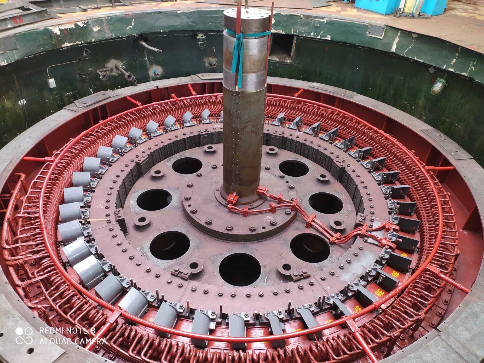
Repairing a generator means restoring its electrical, magnetic, mechanical and thermal characteristics as a whole. Depending on the machine’s type and power, this can involve diagnosing and rewinding the stator or rotor, repairing the excitation system, the slip rings or the rotating rectifier, restoring the shaft and bearings, dynamic balancing, and a full cycle of tests.
A generator cannot be considered properly repaired just because its windings show high insulation resistance, the rotor turns freely, and the machine produces a voltage. After repair it must deliver rated voltage and power, hold stable regulation, keep the phases symmetric, run with normal vibration, and synchronize reliably with the grid.
It is especially important to find the root cause of the failure — simply rewinding the stator or rotor without fixing a faulty excitation system, disrupted cooling, misaligned bearings, or malfunctioning protection can let the repaired machine fail again.
In industrial power generation, synchronous generators are repaired most often — turbogenerators, hydro generators, diesel and gas-piston generators. A turbogenerator typically has a horizontal shaft, a cylindrical rotor, and a high running speed — repair demands special attention to the rotor forging, the retaining rings, and critical speeds.
A hydro generator more often has a vertical shaft, a large-diameter salient-pole rotor, a thrust bearing, and guide bearings — repair focuses on pole fastening, the roundness of the stator and rotor, and aligning the whole assembly. A diesel generator typically has brushless excitation with a rotating diode bridge and an automatic voltage regulator (AVR) — typical problems include no output voltage, a faulty AVR, blown diodes, and lost residual magnetism.
A stator winding breakdown can result from insulation aging, local core overheating, a loose coil in the slot, high partial-discharge activity, an overvoltage, or a water leak from the cooler. Repairing only the point of breakdown without fixing the underlying cause risks a repeat failure.
Common causes of generator damage include a network short circuit, an internal phase-to-phase or interturn short, overload, unbalanced load, lost or excessive excitation, a synchronizing error, overheating, lost cooling, vibration, insulation aging, and a faulty AVR or rotating diodes.
Before teardown, fault recorder traces, phase currents and voltages, zero-sequence current, and field current and voltage are all analyzed — this helps distinguish an internal generator fault from an external short circuit, an excitation-system error, or a mechanical problem in the prime mover.
If condition allows, stator and rotor insulation resistance, the absorption ratio and polarization index, phase resistance and symmetry, and the exciter and diodes are all checked. An interturn defect in a small part of the winding can barely change overall resistance, so a surge test, inductance comparison, and partial-discharge monitoring are used as well.
The stator is checked for a breakdown to frame, a phase-to-phase or interturn short, a broken conductor, a loosened connection, and partial discharge — using a megger, a high-voltage withstand test, a surge test, partial-discharge measurement, and a dissipation-factor (tan δ) test. Insulation can have high overall resistance while still hiding local air voids where partial discharges occur at operating voltage, gradually eroding the material.
The core is checked for a loosened stack, shifted laminations, corrosion, and inter-laminar shorts — damaged inter-laminar insulation causes local heating that can overheat the winding and cause a repeat breakdown even after a good rewind.
The rotor is checked for a winding-to-shaft short, an interturn short, pole asymmetry, and damage to the interpole connections or the damper winding. For a salient-pole rotor, it is worth measuring each pole coil’s resistance and comparing the voltage drop across each pole under a controlled current — reduced resistance points to an interturn short, while raised resistance points to a weak joint or a cracked conductor.
Poles must alternate north-south — a polarity error at one pole distorts the magnetic field, causing asymmetric voltage, vibration, and overheating. For a turbogenerator’s cylindrical rotor, the slot section, the retaining rings, and thermal stability all need special attention, since some defects only appear under heat or at operating speed.
For a brush-type system, check the slip rings, brushes, spring pressure, and rocker — sparking can result from ring run-out, the wrong brushes, or excessive field current. For a brushless system, each rotating diode is checked for forward voltage drop, reverse resistance, and thermal damage — a diode can test fine at low current but fail under load or when hot, so once one diode breaks down the whole set needs assessing.
The automatic voltage regulator (AVR) is checked for power supply, stability, its response to load changes, and the forcing function — a winding should never be blamed for missing voltage without first checking the AVR and the excitation system. After long idle periods, a short circuit, or disassembly, residual magnetic flux can be too weak for self-excitation — the telltale sign is a complete lack of voltage with otherwise sound main windings.
The shaft, bearing journals, coupling, pole fastenings, and balance weights are checked — run-out of the bearing journals, coupling seat, and slip rings is measured. A generator may have rolling-element bearings, plain bearings, tilting-pad or guide bearings, and a thrust bearing on a hydro generator — babbit, the oil wedge, clearances, and the insulation of bearings electrically isolated against shaft currents all get checked separately.
The air gap is measured at several points around the circumference and along the axis — an uneven gap causes unbalanced magnetic pull, vibration, local heating, and can even bring the rotor into contact with the stator. Causes of unevenness include a bent shaft, worn bearings, a shifted stator or rotor, incorrect alignment, or frame distortion.
Local stator repair is possible when the damage is limited, the remaining insulation has enough service life left, the core is undamaged, and the other coils pass testing — this can mean replacing one coil or repairing a lead or a phase connection. A full rewind is warranted for general aging, numerous defects, significant overheating, or widespread partial discharge.
Before teardown, the slot count, pole count, winding type, pitch, turn count, and connection scheme must all be recorded — an old coil may have deformed, overheated, or been altered during a previous repair, so the data needs verifying against drawings and several coils rather than copied from one section.
Stator impregnation — by dipping, vacuum, or vacuum-pressure (VPI) methods — provides dielectric strength, binds the winding, and improves heat transfer. New insulation cannot compensate for insufficient cooling: a disrupted air or water flow overheats individual coils, accelerates aging, and causes a repeat breakdown, so repair often includes cleaning ventilation ducts, repairing air coolers, and checking the leak-tightness of water-cooled windings where the design includes them.
After repair, the rotor’s mass distribution changes because of new coils, insulation, resin, bands, and rotating-rectifier diodes — even coils of identical mass can have their center of mass in a different position, so dynamic balancing is mandatory. A turbogenerator’s cylindrical rotor may need high-speed balancing that passes through critical speeds.
A rotor can be well balanced cold yet vibrate once it warms up, from uneven thermal expansion or an interturn defect — this is called thermal imbalance, and cold balancing alone cannot catch it.
The generator must be correctly aligned with its drive, accounting for thermal growth during operation. Testing starts with no excitation applied — this separates mechanical problems from electromagnetic ones — then excitation is applied gradually while current, voltage, and AVR behavior are monitored.
The open-circuit characteristic — voltage against field current — is recorded and compared to the factory curve; deviations can point to a wrong turn count or shorted rotor turns. Before synchronizing with the grid, phase sequence, voltage, frequency, and phase angle must all match — a synchronizing error can produce a current and torque surge severe enough to damage the coupling or bend the shaft.
No-load running can miss defects in parallel branches, overheating contacts, or regulator instability under load — so a load test with monitoring of active and reactive power, temperature, and vibration is a mandatory final stage.
| Symptom | Likely cause | What to check |
|---|---|---|
| No output voltage | Lost residual magnetism, a faulty AVR | The excitation scheme, residual magnetism |
| Voltage too low | Insufficient excitation, a rotor interturn short | The AVR, the rotor winding |
| Voltage too high | A faulty AVR, wrong feedback signal | The regulator, the sensing circuit |
| Voltage unstable | Poor brush contact, excitation ripple | Brushes, rings, the AVR |
| Vibration rises with excitation | Uneven air gap, shorted rotor turns | Pole polarity, the air gap |
| Stator overheats | Wrong turn count, poor cooling | The winding, ventilation |
| Rotor overheats | An interturn short, excessive field current | Pole resistance, the AVR |
| Sparking on the slip rings | Ring run-out, wrong brushes | Ring geometry, the brush gear |
The most common cause is lost residual magnetism or a faulty automatic voltage regulator (AVR), not a winding defect.
Once one diode breaks down, the rest carry a higher load and can fail soon after — so the whole set and current symmetry need assessing.
No. Insulation can have high resistance while hiding local air voids with partial discharge, or an interturn defect, that a megger simply cannot show.
New coils, insulation, resin, and rotating-rectifier diodes shift the mass distribution even when the parts’ nominal mass is identical.
Some defects — an open parallel branch, overheating contacts, regulator instability — only show up under real load.
A current and torque surge can result, severe enough to damage the coupling, bend the shaft or windings, and trip protection.
EPR (Elektropromremont) performs comprehensive diagnostics, repair and testing of synchronous generators — turbogenerators, hydro generators, diesel and gas-piston generators.
The scope of work includes:
This material is for informational purposes. The values, diagnostic methods, scope of work and recommendations given here are general and do not replace the manufacturer’s technical documentation. The final decision for a specific machine is made from its own diagnostics and inspection, taking into account its type, power, design, duty, operating history and applicable standards.
We run comprehensive diagnostics, pin down the root cause of the fault, and carry out the repair needed with a full test cycle.