What is rotor balancing?
The process of determining and correcting an uneven mass distribution relative to the rotation axis.
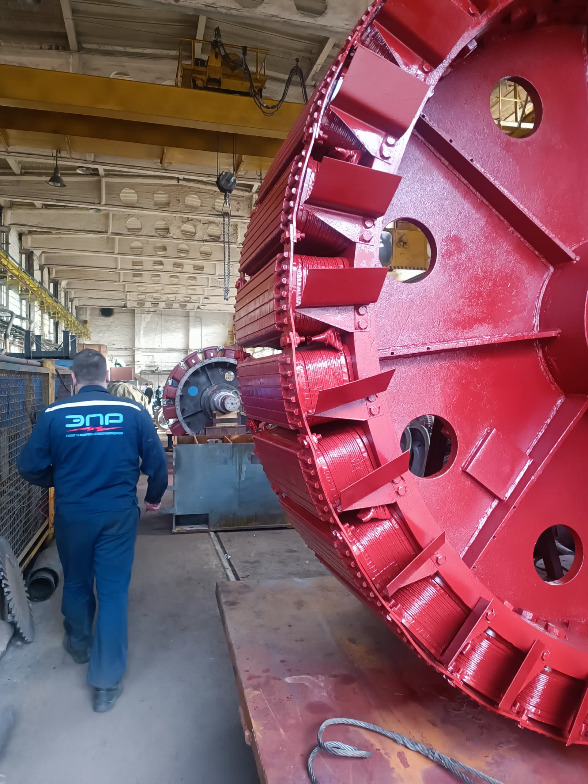
Rotor balancing is one of the key operations in a motor repair. The vibration level, bearing service life, air-gap stability, coupling operation, and the reliability of the whole electric machine all depend on the correct distribution of mass relative to the rotation axis.
An unbalanced rotor creates a centrifugal force that grows with the square of the rotational frequency. So a defect that is almost unnoticeable when turning the shaft slowly by hand can cause dangerous vibration at operating speed. Improper balancing can lead to:
However, increased vibration does not always mean imbalance. Similar symptoms can be caused by a bent shaft, misalignment of the unit, soft foot, a loosened mount, a bearing defect, an oval fit, misaligned bearing endshields, an uneven air gap, rotor damage, electromagnetic asymmetry, structural resonance, a half-coupling defect, or problems with the driven equipment.
So a balancing check should not just confirm the presence of vibration — it should answer several questions:
To check the balancing of a motor rotor, you need to:
Low vibration of the assembled motor does not always prove the rotor is correctly balanced. At the same time, increased vibration is not always a consequence of rotor imbalance.
Imbalance is a condition where the rotor’s principal central axis of inertia does not coincide with its axis of rotation. In simple terms, the rotor’s mass is unevenly distributed, so a centrifugal force arises during rotation. Imbalance is characterized by the product of the unbalanced mass and the radius at which it sits (U = m·r), so the same imbalance value can come from a large mass at a small radius or a small mass at a large radius — for example, 10 g at a 100 mm radius creates the same imbalance as 20 g at a 50 mm radius.
During rotation, the unbalanced mass creates a centrifugal force that depends on the square of the angular velocity (F = m·r·ω²). Doubling the rotational frequency roughly quadruples the centrifugal force. That is why balancing is especially critical for two-pole motors, high-speed rotors, long rotors, turbomachinery, rotors with heavy fans, rotors with large half-couplings, machines with small bearing clearances, and equipment with strict vibration requirements.
Occurs when the rotor’s center of mass is offset from the rotation axis, but the imbalance can conventionally be corrected in a single transverse plane. When the rotor is set on knife-edge supports, the heavy spot tends to settle at the bottom. Typical for narrow disks, short fans, pulleys, flywheels, and short rotors with a low length-to-diameter ratio. It can sometimes be detected on knife-edge or roller supports without spinning at operating speed, but static balance does not guarantee dynamic balance for a long rotor.
Occurs when equal but oppositely directed imbalances sit in different planes of the rotor. The center of mass can remain on the axis, so a static check does not always turn the rotor heavy-side-down. During rotation, such a system creates a moment that rocks the rotor and loads the supports in opposite phases — it cannot be fully eliminated by correcting a single plane.
The most common real-world state of a long rotor — a combination of static and couple imbalance. Eliminating it usually requires at least two correction planes. Dynamic balancing determines the imbalance on the drive side and on the opposite side, the angular correction position in each plane, and the residual imbalance after correction.
A rotor is considered rigid within a given operating range if its elastic deformation during balancing does not significantly affect the imbalance distribution. Such a rotor can be balanced at a speed below the operating speed, and the result remains valid at operating conditions. Most industrial motor rotors are balanced as rigid rotors.
Changes shape under centrifugal forces when approaching critical speeds. Ordinary low-speed two-plane balancing is not enough for it — multi-plane balancing, high-speed balancing, mode-shape monitoring, a special stand or vacuum chamber, modal analysis, and monitoring during run-up and coastdown may be needed. The rigid-rotor method cannot automatically be applied to long, high-speed rotors of generators, turbines, or compressors.
| Feature | Static balancing | Dynamic balancing |
|---|---|---|
| Rotational speed | Very low or none | The rotor spins |
| Number of planes | Usually one | Usually two or more |
| Detects the heavy spot | Yes | Yes |
| Detects couple imbalance | No | Yes |
| Suitability for long rotors | Limited | The primary method |
| Assesses the supports’ reaction | No | Yes |
| A balancing machine is needed | Not always | Yes |
| Accuracy for a motor rotor | Insufficient as the sole method | Significantly higher |
For an industrial motor rotor, a static check can be used as a preliminary step, but the final confirmation should usually be done dynamically.
After balancing, some small unevenness in mass distribution always remains — that is the residual imbalance. It is assessed separately for each plane, as specific residual imbalance, according to the balance quality grade, and taking into account the rotor’s mass and operating speed. The goal of balancing is not to reach a mathematical zero, but to ensure an acceptable residual imbalance.
Specific residual imbalance is defined as the ratio of residual imbalance to the rotor’s mass — this figure has the dimension of an equivalent center-of-mass displacement. The higher the operating speed, the smaller the allowable specific imbalance must be for the same level of dynamic loading.
The balance quality grade characterizes the acceptable level of residual imbalance for a given rotational speed. The grade choice depends on the rotor type, rotational frequency, machine design, support stiffness, the equipment’s purpose, manufacturer requirements, the allowable vibration level, and operating conditions. The same quality grade cannot be assigned to a slow large rotor, a high-speed two-pole rotor, a fan, a DC machine armature, a generator rotor, and a rotor with a half-coupling.
The main source of requirements should be the drawings, the manufacturer’s technical specifications, repair documentation, the process card, applicable standards, and the customer’s requirements.
The vibration of an assembled motor does not depend on the rotor alone. The result is influenced by the bearings, bearing endshields, the foundation, soft foot, alignment, the coupling, cable and piping loads, resonance, housing stiffness, the air gap, the supply, the driven equipment, and any drive.
Possible situations:
So a motor vibration test matters, but it does not replace balancing the rotor on a machine.
Typical signs can include:
However, the 1× component can also be related to misalignment, a bent shaft, eccentricity, looseness, resonance, a mechanical or electromagnetic imbalance, coupling runout, or an incorrectly mounted sensor. So the spectrum needs to be analyzed together with the phase, the waveform shape, and the results of a mechanical inspection.
The main causes:
Balancing is needed:
Balancing must not be used to mask other defects. The following need to be fixed first:
A rotor with mechanically unstable parts can show a different imbalance on every spin.
Before balancing, the shaft condition, radial and axial runout, fit ovality, taper, center holes, the core, squirrel-cage bars, end rings, fans, lashing, the winding, balance rings and weights, the commutator, slip rings, keyways, threaded connections, and possible friction points all need to be checked. For critical rotors, non-destructive testing of the shaft and stressed parts is worth doing.
A balancing machine responds to the forces generated during rotation. It cannot always distinguish mass imbalance from a bent shaft, fit eccentricity, runout of a bearing surface, roller instability, or rotor deformation. If the shaft is bent, balance weights can reduce the support reaction at the balancing speed, but the geometric runout remains, the load on the bearings does not disappear, the problem can return at a different speed, and the air gap, seals, and coupling will not work correctly. So significant runout needs to be fixed before final balancing.
The rotor needs to be balanced in a configuration as close as possible to the operating one. It has to be determined whether the balancing assembly includes the fan, balance rings, slip rings, the commutator, the half-coupling, the key, locking elements, mounting bolts, protective disks, seal rings, the impeller, and other parts that rotate with the shaft. If some parts will be balanced separately, the correct relative angular position must be ensured during final assembly.
The fan can be a significant source of imbalance due to deformed blades, buildup, corrosion, weld repair, uneven blade mass, an incorrect fit, hub eccentricity, or a shifted mount. Before balancing the rotor, the fan needs to be cleaned, inspected, checked for geometry, runout, and mounting, and confirmed free of cracks — balancing a dirty fan makes no sense, since the mass distribution will change once it is cleaned.
The keyway is one of the most common sources of balancing errors. The rotor, the half-coupling, a pulley, or another part can be balanced with a full key, a half key, no key, or a manufacturer-specific method. If the shaft and half-coupling were balanced under different conventions, assembly will create an artificial imbalance. It matters to document the keyway convention used, the key’s length, material, actual configuration, the keyway’s condition, and its position during balancing — a full key should never be left arbitrarily in an open slot without understanding the method.
Dynamic balancing uses soft-bearing machines, hard-bearing machines, horizontal and vertical balancing machines, below-resonance and above-resonance systems, dedicated armature machines, high-speed balancing rigs, and mobile in-situ balancing systems using the rotor’s own bearings. A horizontal two-plane balancing machine is the most common choice for a motor rotor.
The supports have a relatively low natural frequency and move noticeably under imbalance; the system measures the supports’ motion. Advantages: high sensitivity, suitable for a wide range of rotors. Limitations: the correct speed matters, precise calibration is needed, the system is sensitive to external vibration.
The supports move very little, and the system measures the reaction forces. Advantages: allows pre-calibration, convenient for series work, stable when changing rotors within a range. Limitations: requires correct geometry input, needs sound sensors and supports, has mass and size limits.
Before mounting the rotor, check the machine’s levelness, the foundation, the mounting, the cleanliness of the supports, the condition of the rollers and their own runout, the state of the belt or cardan drive, the sensors’ condition, the calibration, the correctness of the electrical connections, the guards, the emergency stop, the allowable rotor mass, the range of journal diameters, and the allowable speed. Extraneous vibration from nearby equipment can affect measurements, especially with a small residual imbalance.
The rotor is mounted on surfaces that provide a stable rotation axis — most often the bearing journals, process journals, special mandrels, trunnions, or balancing arbors. Before mounting, clean the journals, check their diameter, ovality, and roughness, confirm there are no burrs, check the rollers, and ensure the correct axial position. The rotor must not touch stationary parts, shift axially during the spin, slip on the rollers, create unstable contact, or exceed the supports’ allowable load.
For the correction to be calculated correctly, the system needs the distance between the supports, the position of the left and right correction planes, the distances from the planes to the supports, the correction radii, the rotor’s mass, the rotor type, the operating speed or quality grade, the units of measurement, and the allowable residual imbalance.
A geometry error can produce the wrong mass or correction angle even if the machine itself is sound. Especially dangerous: swapping the left and right planes, an incorrect distance sign, a mistaken radius, entering the diameter instead of the radius, the wrong length unit, and an incorrect rotor mass.
Correction planes need to be structurally suitable for adding or removing mass, have a sufficient radius, be rigidly connected to the rotor, avoid creating a dangerous stress concentration, allow reliable weight retention, and match the drawing and the process. Typical planes: balance rings, core ends, dedicated slots, fan disks, balance washers, process bosses, and pre-drilled holes. The shaft, bearing journals, or stressed elements must never be drilled arbitrarily.
Used when the rotor is short, the main imbalance is concentrated in one plane, the length-to-diameter ratio is small, the design behaves like a narrow disk, the support reactions allow that model, and the manufacturer’s method permits it. Correction is done in one plane by adding, removing, or moving mass. A single plane is often not enough for a long motor rotor.
Allows the static and couple components of a rigid rotor’s imbalance to be removed. The machine determines a separate correction for the drive-side plane and the opposite-side plane — for each plane the system shows the correction mass, angle, radius, and residual imbalance. After the correction is applied, a re-spin and fine-tuning follow.
If the machine or a mobile system has no ready calibration for a specific configuration, a trial weight is used to determine how the rotor and the measuring system respond to a known mass change. A trial weight needs a precisely known mass, a known radius, a precise angular position, reliable temporary attachment, a sufficient effect on the signal, and a safe design. Too small a weight will not produce a reliable change; too large a weight can create dangerous vibration.
When choosing the trial weight’s mass, the rotor’s mass, the speed, the radius, the initial vibration, the support stiffness, the allowable load, the instrument’s recommendations, and experience with similar rotors are all taken into account — a random weight without a prior estimate should not be used.
A temporary weight must be secured against being thrown off — possible methods: a bolted mount, a dedicated balancing slot, a process clamp, or another solution provided by the design. Unreliable methods must be avoided, especially weak adhesive, unengineered wire, a magnet without mechanical fixation, a weight mounted on a contaminated surface, or attachment near stationary parts without clearance checked. Before spinning, check the strength, the direction of the centrifugal force, the clearance, the maximum allowable speed, and the guarding of the zone.
Uses bolted weights, balance washers, special plates, weights in slots, or factory balancing elements. Advantages: adjustability, no removal of base material, easy re-tuning. Disadvantages: risk of loosening, location constraints, the need for reliable fixation, added load on the part.
Uses drilling, milling, grinding, or removing material from dedicated bosses. Advantages: no additional fixture needed, a permanent correction. Disadvantages: irreversibility, risk of weakening the part, danger of damaging the winding or core, constrained by the drawing.
Existing balance weights are repositioned — allowed only when the slots, threads, and retention elements are sound.
If the machine shows a correction at one radius but the weight can only be mounted at another, the same imbalance moment is preserved (m₁·r₁ = m₂·r₂) — the larger the correction radius, the smaller the required mass. The recalculation needs to account for the weight’s actual center of mass, the exact radius, the angular position, the part’s thickness, and any offset between planes.
If the correction is done by drilling, the volume and mass of the material being removed need to be determined, taking into account the hole diameter, depth, material density, the radius of the removed volume’s center, the allowable depth, the minimum edge distance, and the part’s strength. Drilling "by eye" without controlling the actual mass removed is not acceptable — for complex holes, milled slots, or several correction points, the combined imbalance vector needs to be calculated.
The balancing machine can show the heavy spot, where to add or remove mass, and the angle either with or against the direction of rotation. Before correcting, it needs to be clearly established where the reference 0° is, from which side the rotor is being viewed, which reference direction is used, whether the system indicates an add or remove location, and whether the planes have been mixed up. A 180° error will worsen the imbalance instead of reducing it.
A stable angular mark is created on the rotor — a keyway, a special scribe line, a mark on the balance ring, a factory mark, or a reference hole. The mark needs to be clear, must not disappear after cleaning, must not damage the part, must stay the same across all spins, and must be noted in the report.
If the rotor shows different imbalance values on every spin, the balancing cannot be considered reliable. Possible causes of instability: a loose part, winding movement, an unstable fan, roller slippage, axial shift, a drive defect, an unstable support, contaminated rollers, electrical interference, an incorrect phase sensor, thermal deformation, proximity to resonance, or insufficient time for the speed to stabilize. Weights should not keep being added arbitrarily until the cause is fixed.
Once the allowable residual imbalance is reached, the result’s accuracy can be confirmed with a check weight: a precisely known weight is mounted in the chosen plane, a spin is run, it is verified whether the system correctly detects the added imbalance, the weight is repositioned or removed per the method, and the result is compared with the calculation. This test helps reveal a calibration error, an incorrect angle, a radius error, low sensitivity, or system instability.
The final check needs to confirm the allowable residual imbalance in each plane, phase stability, repeatability, the reliability of the weights, the absence of dangerous vibration and friction, and the correct operation of the machine’s drive. A "0" reading on the screen without a report and verification is not sufficient proof of a quality balancing job.
Once the rotor is installed in the motor, a no-load test is run. Vibration is measured at the bearing endshield on the drive side and the opposite side, in the horizontal, vertical, and axial directions, on the housing, and — if needed — directly on the shaft with non-contact sensors. The overall level, the spectrum, the 1× amplitude, the phase, the rotational frequency, the temperature, the time after startup, and the measurement direction are all recorded.
Amplitude shows the size of the oscillation, while phase shows its position relative to the rotor’s rotation. A stable phase at 1× often supports the imbalance hypothesis. An unstable or sharply changing phase can indicate looseness, friction, resonance, an unstable speed, a moving part, electrical instability, or an error in the tachometer mark. Phase analysis is especially important when balancing in the rotor’s own bearings.
Imbalance is often predominantly radial, at 1×, with a stable phase and a proportional increase with speed. Misalignment can show up as high axial vibration, 1× and 2× harmonics (sometimes higher), different phases on the two sides of the coupling, heating of the coupling or bearing, and a change after alignment. But the real-world signs can overlap, so a comprehensive check is needed.
A bent shaft can also produce a strong 1× component. Signs of a possible bend: elevated indicator runout, phase-consistent runout across several cross-sections, unstable balancing, vibration persisting after correction, a change in the air gap, seal problems, and coupling runout. So shaft geometry must always be checked before balancing.
Under resonance, even a small imbalance can produce very high vibration. Signs: a sharp rise in amplitude within a narrow speed range, a significant phase shift when passing through the critical frequency, a drop in vibration as speed increases further, and high sensitivity to foundation stiffness. Adding balance weights can reduce the excitation force but does not eliminate the structure’s resonance itself.
Can produce an unstable phase, rotational-frequency harmonics, impacts, a non-linear dependence on speed, and different results on repeated startups. The feet, foundation bolts, bearing endshields, covers, bearing fits, core retention, the fan, and the balance weights all need to be checked — balancing an unstable system does not give a stable result.
Can also create radial forces due to an uneven air gap, an interturn short, a rotor defect, unbalanced voltages, winding asymmetry, or eccentricity. Practical signs: vibration changes sharply when power is cut, electrical frequency components are present, the level depends on voltage, there is current asymmetry, and vibration changes with load differently than expected for a purely mechanical imbalance.
A coastdown test helps distinguish an electromagnetic component from a mechanical one: during coastdown after power is cut, the vibration amplitude and phase are monitored as speed falls. If a particular vibration disappears almost immediately after power is cut, its source may be electromagnetic; if it decreases smoothly along with the speed, a mechanical origin is more likely.
Sometimes the rotor cannot be removed, or a balancing machine cannot reproduce the real conditions. In that case, field balancing of the assembled machine is used — this requires a vibration analyzer, a phase sensor, a tachometer mark, the ability to safely mount trial weights, access to the correction planes, and a stable operating regime.
Advantages: it accounts for the real supports, the half-coupling or impeller, and can reduce the unit’s vibration without disassembly. Disadvantages: the result includes the whole machine, other defects are hard to separate out, access is limited, the risks are higher, a stable speed is needed, and the requirements for the rotor itself are not always achievable. Field balancing must not replace repairing a bent or damaged rotor.
Single-channel field balancing uses one vibration sensor and can suit a short rotor, a single correction plane, or a simple mechanical system. Two-channel or multi-channel balancing allows simultaneously monitoring the response of two supports and performing two-plane balancing — this is better for long rotors, motors with two accessible planes, and units with a complex vibration pattern.
Causes of deterioration after installation: a different half-coupling, an incorrect key, misalignment during installation, contamination of a fit, fan deformation, a shifted balance weight, an impact during transport, a bent shaft, loosened parts, incorrect assembly, a different axial position of parts, or thermal deformation. So a control vibration check is needed after final assembly.
Causes of a change in balance after warm-up: thermal bowing, winding movement, uneven expansion, a change in the fan’s fit, loss of grease or moisture, deformation of the lashing, a change in support stiffness, bearing heating, or a change in the air gap. If a cold machine runs stably but 1× vibration rises after warm-up, the thermal behavior of the rotor and the whole unit needs to be checked.
Before balancing, the cage bars, end rings, signs of prior repair, cracks, casting porosity, the core, the fan, the shaft, and the balance elements are all checked. After a cage repair, the mass distribution can change significantly — this especially applies to replacing individual bars, brazing, weld overlay, end-ring repair, crack removal, and local machining.
Has additional elements: the winding, end windings, lashing, slip rings, leads, and winding retention. Before balancing, the symmetry of the winding layout, the impregnation, the fixation of the end windings, the lashing’s condition, the slip rings’ alignment, the absence of loose conductors, and connection reliability all need to be checked. A loosened winding can shift position under centrifugal forces, making balancing unstable.
For the armature, the commutator, the winding, the lashing, the wedges, the fan, the shaft, the fits, and the balance rings are checked. The commutator has a significant mass and can substantially affect the imbalance. After commutator replacement, turning, rewinding, lashing replacement, or repair of sections, the armature needs to be rebalanced; the commutator’s radial runout also needs to be checked, since balancing does not correct its geometric ovality or eccentricity.
For synchronous rotors, the poles, field coils, damper elements, lashing, fans, slip rings, pole shoes, and mounting parts are checked. A difference in pole or coil mass can create significant imbalance — after repairing one pole, its mass, material distribution, geometry, relative position, and mounting strength need to be assessed.
There are several options: balancing the rotor without the half-coupling, balancing the half-coupling separately, balancing the rotor together with the half-coupling, or a final field balancing of the whole unit. The choice depends on the fit, the repeatability of the installation, the keyway convention, manufacturer requirements, the speed, and the coupling’s design. If the half-coupling is mounted in a different angular position each time, joint balancing can lose its meaning without clear marking.
More than two planes may be needed for a flexible rotor, a rotor with several critical mode shapes, a very long rotor, a high-speed machine, a complex rotor with widely spaced masses, or a rotor that changes shape at operating speed. This kind of work should not be treated as ordinary two-plane balancing without dedicated analysis.
The balancing speed is chosen based on the machine type, the rotor’s mass, its diameter, the bearing journals, stiffness, critical speeds, the drive, safety requirements, and the system’s calibration. For a rigid rotor, the balancing speed can be much lower than the operating speed, but it needs to provide a sufficient signal, avoid passing through a dangerous resonance, stay within the machine’s limits, avoid slippage, and remain stable during measurement.
A rotor spinning on a machine is a source of elevated hazard: risks include a trial weight flying off, fan destruction, the rotor coming off the supports, entanglement of clothing, drive-belt failure, contact with rotating parts, a loose element flying off, and excessive vibration. Guards need to be used, the mounting checked, standing outside the possible throw zone maintained, a remote start applied, an emergency stop available, speed increased gradually, the allowable regime not exceeded, the machine stopped on instability, and the rotor not touched until it has fully stopped.
The balancing machine needs to be stopped immediately on a sharp rise in vibration, an impact, a metallic noise, rotor displacement, roller slippage, axial shift, a loosened drive, a weight coming off or shifting, friction against stationary parts, an unstable signal, guard damage, or exceeding the allowable load. The spin should not be continued in the hope that the system will "stabilize."
| Observation | Possible cause | Next action |
|---|---|---|
| High stable vibration at 1× | Imbalance | Check the phase and perform balancing |
| Significant shaft runout | Bending or eccentricity | Fix the geometric defect |
| Different results on every spin | A moving part or an unstable support | Stop balancing and inspect |
| Vibration increased after a weight | Wrong angle or plane | Check the reference system |
| One support reacts much more strongly | A local or couple imbalance | Check the geometry and two-plane model |
| The motor vibrates after machine balancing | Alignment, coupling, foundation, or assembly | Diagnose the assembled unit |
| Vibration rises after warm-up | Thermal bowing or a moving part | Run a thermal and phase analysis |
| Vibration drops sharply after power cut | An electromagnetic component | Check the windings, air gap, and supply |
| A significant 2× component | Misalignment or another defect | Check the alignment |
| Significant harmonics | Looseness, friction, or non-linearity | Check the mounting and clearances |
| Balance weights keep changing | An unstable rotor | Check the lashing, fan, and winding |
| Vibration is high only near a certain speed | Resonance | Run a run-up/coastdown test |
| 1× appeared after coupling installation | The coupling, key, or fit | Check the runout and keyway convention |
Things to avoid:
Possible causes: incorrect alignment, soft foot, a coupling defect, the bearings, endshield deformation, an uneven air gap, foundation resonance, electromagnetic asymmetry, or an assembly error. What is needed is diagnostics of the assembled unit, not an automatic re-balance.
Possible causes: a loosened fan, a moving balance weight, roller slippage, axial displacement, a phase-sensor defect, an unstable speed, or winding movement. Correction should not continue without locating the cause.
Causes: the add and remove locations were swapped, an angle error, an incorrect zero, a plane error, an incorrect mass or radius, or an unstable rotor. The input data and reference system need to be checked.
The contamination had mass and was part of the earlier distribution. Only a clean, dry rotor in a stable state should be balanced.
Possible causes: resonance, flexible-rotor behavior, thermal bowing, a part shifting under centrifugal force, or insufficient low-speed balancing. A run-up, coastdown, and critical-speed analysis is needed.
The fits, internal clearance, mounting, endshield misalignment, shaft runout, alignment, preload, and foundation condition all need to be checked. The rotor itself may have remained balanced.
This can indicate incorrect geometry in the system, an incorrect radius, an angle error, a significant mechanical defect, a missing part, a deformed fan, the wrong configuration, or a large initial imbalance after repair. The rotor needs to be re-checked before adding an excessive mass.
After the work is complete, it is necessary to confirm the residual imbalance is acceptable, repeat the control spin, verify repeatability, securely fix the weights, lock threaded elements, check the clearances, inspect the material-removal spots, confirm there are no cracks, re-measure the runout, check the condition of the journals, record the angular marks, issue the report, check the motor’s vibration after reassembly, and check the unit under load after installation.
The report should include:
The process of determining and correcting an uneven mass distribution relative to the rotation axis.
Imbalance characterizes mass distribution, while runout is the geometric displacement of a surface during rotation.
A certain vibration response can be reduced, but the geometric defect will remain. The correct fix is to restore the shaft first.
Sometimes, for a narrow disk. Most long motor rotors need two-plane dynamic balancing.
Dust, oil, varnish, or buildup all have mass. The balance will change once it is cleaned.
Yes, if the mass distribution of the winding, lashing, or geometry changed — the rotor needs to be re-checked and usually dynamically rebalanced.
It is the imbalance that remains after correction — due to measurement errors, the discreteness of the correction, part geometry, and physical limits.
A vibrometer assesses the whole machine’s operation, but does not always precisely determine the rotor’s own residual imbalance.
It lets you determine the angular position of the imbalance and distinguish between different mechanical phenomena.
Stop the balancing and check the rotor, the supports, the drive, the sensors, and the mounting.
Elektropromremont performs comprehensive diagnostics, repair, and balancing of rotors for industrial electric machines. The scope of work includes:
Checking rotor balancing is not just a vibration assessment, and not a one-off installation of a balance weight. A quality job needs to include rotor inspection, a runout check, control of the shaft and fits, the correct choice of configuration, the keyway convention, correct mounting on the machine, precise geometry entry, determining the imbalance in the relevant planes, safe correction, a repeatability check, confirmation of the residual imbalance, reliable fixation of the weights, and a check after the motor is reassembled.
A correctly balanced rotor reduces the dynamic loads on the bearings, the housing, the foundation, and the driven equipment. But balancing only delivers a reliable result when the shaft is straight, the fits are aligned, the parts are secured, and the machine itself has no other mechanical or electromagnetic defects.
The main principles:
This material is for informational purposes. The values, diagnostic methods, scope of work and recommendations given here are general and do not replace the manufacturer’s technical documentation. The final decision for a specific machine is made from its own diagnostics and inspection, taking into account its type, power, design, duty, operating history and applicable standards.
We run a complete inspection, two-plane dynamic balancing, and post-assembly vibration control, with a full report.