What is a rotor?
The rotor is the rotating part of an electrical machine that interacts with the stator’s magnetic field and transmits mechanical torque through the shaft.
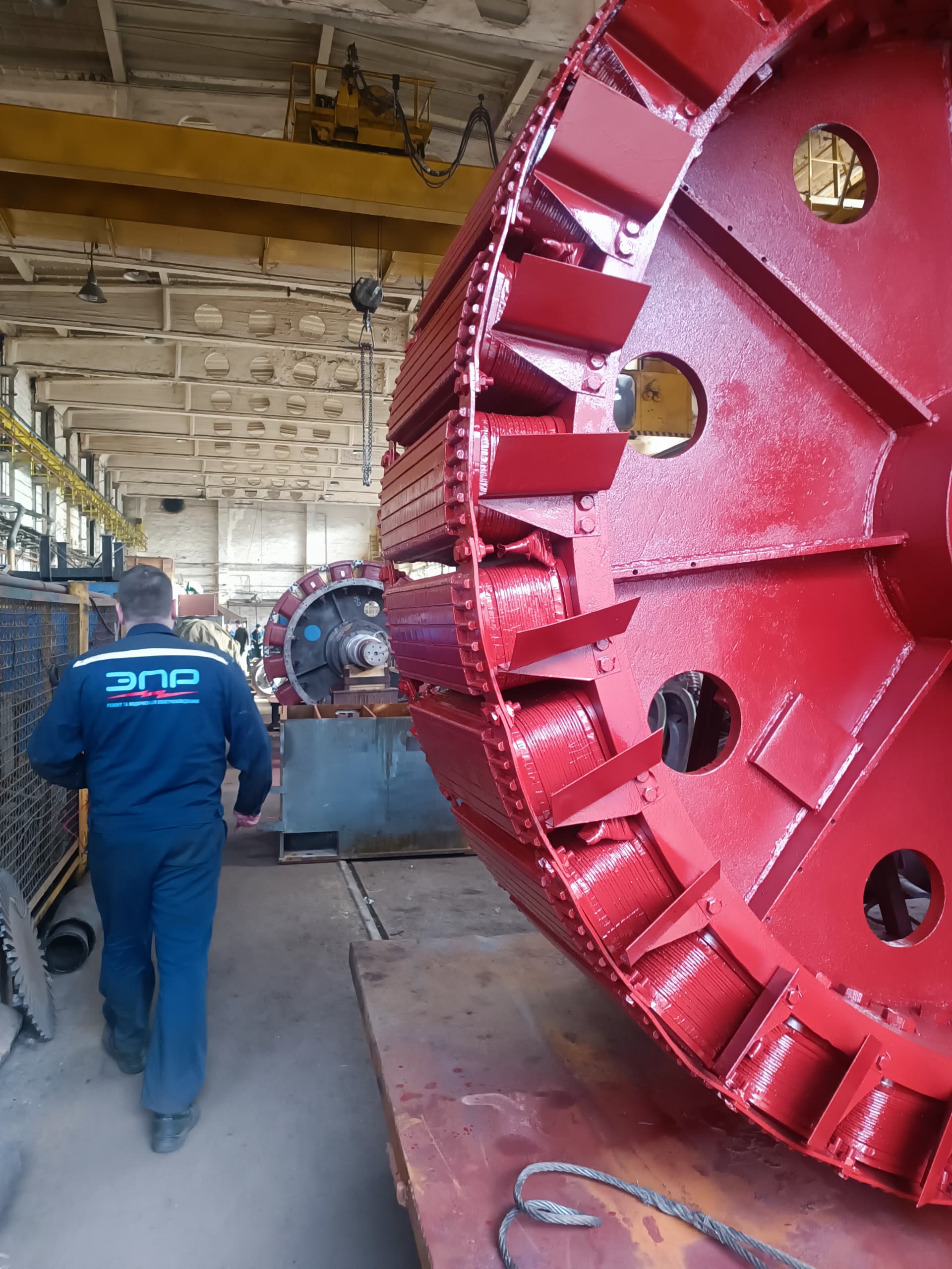
A motor rotor is the rotating part of an electrical machine, located inside the stator and forming its electromagnetic system together with it.
In motoring mode, electromagnetic interaction between the stator and rotor fields produces rotating torque, transmitted through the shaft to a pump, fan, compressor, gearbox, conveyor, crusher, traction drive, machine tool, generator, or another driven mechanism. In generator mode, the process runs in reverse: a mechanical prime mover turns the rotor, and its magnetic field interacts with the stator, converting mechanical energy into electrical energy.
Rotor design depends heavily on the type of electrical machine. A rotor can be:
That is why the term "rotor" describes not a single specific part, but an entire class of rotating assemblies found in electrical machines.
The rotor is the rotating part of a motor or generator that transmits mechanical torque through the shaft. A typical rotor can consist of:
A rotor operates simultaneously under electromagnetic torque, centrifugal forces, vibration, thermal deformation, load from the driven mechanism, radial and axial forces, forces from a gearbox or coupling, and transients during starting and faults. That is why a rotor’s technical condition determines not only the machine’s electrical characteristics, but also its mechanical reliability.
In most motors, the rotor sits inside the stator. In simplified form, the construction can be represented as:
frame → stator → air gap → rotor → shaft
A small air gap separates the stator from the rotor. The rotor turns without touching the stator; its position is maintained by bearings fitted in bearing brackets, pedestal bearings, special supports, or the bearing assemblies specific to a given machine.
A rotor’s main job is to interact with the stator’s magnetic field and produce or transmit electromagnetic torque. In a motor: electrical energy → an electromagnetic field → rotor torque → mechanical energy. In a generator: mechanical energy → rotor rotation → an electromagnetic field → the stator’s electrical energy. The rotor’s function depends on the machine type.
Although designs vary across machines, a few core elements can be identified:
The shaft is the rotor’s main mechanical element. It can carry the core, a fan, bearings, a coupling, a pulley, a gear, slip rings, the pole system, an exciter, and other components. The shaft transmits torque, radial and axial loads, bending forces, and dynamic loads.
The bearing journals, fillets, keyways, threaded sections, coupling and gear fits, diameter transitions, the section under the core, the fan-mounting area, and taper surfaces all need particular attention. Mechanical stress can concentrate in these zones — this is where fatigue cracks, fretting, wear, scoring, and residual deformation often show up.
In many electrical machines, the rotor has a laminated core built up from electrical-steel sheets, similar to the stator core. The goal of lamination is to reduce eddy currents and losses. The core can be press-fitted directly onto the shaft, mounted on a sleeve, built from separate stacks, have ventilation ducts, and be held in place by pressure plates.
Rotor slots can hold squirrel-cage bars, a wound-rotor winding, a field winding, or damper bars. Slot shape affects the machine’s electromagnetic characteristics — an induction motor can use round, oval, deep, double, or specially profiled slots, which lets designers influence starting torque, starting current, slip, rotor heating, and the operating characteristic.
By construction, rotors fall into:
This is one of the most common rotor types in industrial motors — used in three-phase induction motors. Its main elements are the shaft, core, bars, short-circuiting rings, and sometimes ventilation blades. The bars and rings form a closed electrical system known as a "squirrel cage."
The stator produces a rotating magnetic field that moves relative to the rotor and induces a voltage in its bars. Since the bars are short-circuited by the end rings, current flows through them. The interaction between the rotor currents and the stator’s magnetic field produces electromagnetic torque, and the rotor begins turning in the direction of the field.
Inducing current in the rotor requires relative speed between the rotor and the stator’s magnetic field. That is why, in motoring mode, rotor speed runs slightly below the field’s synchronous speed — this difference is called slip. If the rotor reached exactly synchronous speed, the relative motion would vanish, the cage’s EMF would approach zero, rotor current would fall, and electromagnetic torque could no longer sustain the load.
The cage consists of bars and end rings. The material can be aluminum, copper, copper alloys, or special materials depending on the design. By manufacturing method, a cage can be cast, welded, brazed, or a combination.
In many production motors, the cage is die-cast from aluminum directly into the core’s slots — the bars, end rings, and ventilation blades (where the design calls for them) are formed at the same time. Advantages: manufacturability, no need for many individual joints, suitability for mass production, and low cost.
High-power motors often use copper bars, joined to the end rings by brazing, welding, or special process methods. Copper has lower electrical resistance, but the cage’s design is set not just by the material’s conductivity but also by the motor’s required starting and running characteristics.
In a wound-rotor induction motor, an insulated three-phase winding sits in the rotor slots, usually connected in a star. The three winding ends are brought out to slip rings. Through the brush gear, starting resistors, adjustable resistances, or special power equipment can be connected to the rotor.
Adding external resistance to the rotor circuit increases starting torque, limits starting current, allows control of the acceleration process, and, in certain schemes, allows speed control. Wound-rotor motors were traditionally used wherever a heavy start was needed: cranes, mills, crushers, conveyors, hoisting mechanisms, and heavy industrial equipment.
Main parts of a wound rotor: the shaft, a laminated core, slot insulation, the three-phase winding, slot wedges, end-turns, bracing, slip rings, and terminals. In structural complexity and repair technology, a wound rotor is closer to a stator than a squirrel-cage rotor.
The winding must withstand significant starting currents, centrifugal forces, heating, vibration, repeated starts, and mechanical displacement during rotation. The slot sections, slot exits, end-turns, brazed joints, and slip-ring connections are all especially critical.
Slip rings provide the electrical connection between the rotor winding and the external circuit. They are mounted on the shaft and insulated from it; rotor current passes through the rings and brushes. Typical defects: wear of the working surface, runout, burning, contamination, insulation damage, loosened contacts, uneven wear, and an inter-ring short.
A salient-pole rotor has clearly distinct magnetic poles. It’s used in synchronous motors, hydrogenerators, synchronous generators, and special machines. Each pole can consist of a pole body, a pole shoe, a field coil, insulation, and fastenings.
DC current flows through the field winding and produces the rotor’s magnetic field. Current can be supplied through slip rings and brushes, from a brushless exciter, or through another excitation system. Typical defects: an interturn fault, a ground fault, an open circuit, overheating, loosened fastenings, and insulation damage from centrifugal forces.
In many salient-pole synchronous machines, damper bars are fitted in the pole shoes, joined by end rings into a cage. Functions: damping rotor oscillations, reducing electromechanical oscillations, and assisting the asynchronous starting of some synchronous motors.
A non-salient-pole rotor has an almost cylindrical outer surface. It is typical of high-speed synchronous machines — the best-known example is a turbogenerator rotor, manufactured as a massive forged body with slots for the field winding. Such rotors must withstand extremely high centrifugal forces, so mechanical strength, retaining-ring condition, turn insulation, balancing, and the absence of cracks are all especially critical.
Hydrogenerators often have large salient-pole rotors, whose main parts can include a shaft, hub or spider, rim, poles, pole coils, a damper system, and fastenings. Such rotors can have a very large diameter, dozens of poles, comparatively low rotational speed, and considerable mass.
In permanent-magnet synchronous motors, magnets produce the rotor’s field. They can be mounted on the rotor surface, inside the rotor, in special slots, or in a combined magnetic system. Such motors are used in servo drives, traction drives, electric vehicles, high-efficiency industrial drives, compressors, and pumps.
Possible permanent-magnet damage: demagnetization, cracking, delamination, corrosion, displacement, and mechanical failure. Causes: overheating, excessive current, a fault condition, centrifugal forces, incorrect assembly, and mechanical impact. Repairing such a rotor requires special technology.
In self-ventilated motors, a fan is often mounted directly on the rotor shaft. Its job is to circulate air across the frame surface, ventilation ducts, core, and winding end-turns. A damaged fan can cause overheating even when the motor’s electrical part is fully sound.
In high-power machines, the core can have ventilation ducts through which cooling gas or air flows. Clogged ducts cause degraded cooling, local overheating, uneven temperatures, and reduced insulation or cage life.
Every rotor has a certain mass distribution relative to its axis of rotation. If the center of mass does not coincide with the rotation axis, imbalance results, producing a centrifugal force as the rotor turns. The higher the speed, the more strongly the imbalance shows up.
An unbalanced rotor can cause vibration, noise, elevated bearing loads, seal damage, loosened fastenings, cracks, reduced motor life, and foundation damage. For high-speed machines, even a small imbalance can have significant consequences.
Static balancing mainly corrects imbalance in a single plane and can be used for narrow rotors. Dynamic balancing accounts for imbalance in two or more correction planes — dynamic balancing is what most industrial rotors receive after a repair.
Balancing is required after:
The rotor rests on bearings. Bearing-assembly condition determines the rotor’s position relative to the stator, air-gap size, vibration, noise level, and mechanical losses. A damaged bearing can let the rotor shift far enough to touch the stator.
The air gap must be large enough for safe rotation, as uniform as possible, and consistent with the machine’s design. A non-uniform gap can result from worn bearings, a bent shaft, core displacement, stator deformation, incorrect assembly, or eccentricity.
Eccentricity means the rotor’s geometric axis does not properly coincide with the stator’s center. With static eccentricity, the minimum gap stays roughly at one position relative to the stator; with dynamic eccentricity, the minimum-gap zone rotates with the rotor. Eccentricity can cause a non-uniform magnetic field, unbalanced magnetic pull, vibration, noise, elevated bearing loads, and rotor-to-stator rubbing.
Rotor-to-stator contact is a fault or a pre-fault condition. Causes: bearing failure, excessive bearing clearance, a bent shaft, incorrect assembly, frame deformation, thermal distortion, or a loosened fit. Consequences: damage to the rotor and stator cores, shorted laminations, overheating, winding destruction, and severe vibration.
The most common include:
During motor starting, rotor current frequency is high, and currents can be substantial. The rotor heats up quickly; after acceleration, the temperature changes. Each start repeats the cycle: heating → thermal expansion → cooling → contraction. With a large number of starts, this creates fatigue loading on the bars, rings, and joints. Especially harsh regimes: a prolonged start, frequent reversals, mechanism jamming, starting under heavy load, and restarting a hot motor.
Signs of broken bars: the motor takes longer to accelerate, starting torque decreases, vibration increases, a periodic pulsation appears, the motor runs hotter, the sound changes, characteristic components appear in the current spectrum, and operation becomes unstable under load. With a single small defect, the motor can sometimes run nearly normally at no load.
An interturn fault occurs between turns of the same coil due to thermal aging, vibration, centrifugal forces, insulation damage, contamination, frequent starts, or a loosened winding. Consequences: local overheating, asymmetry, reduced torque, vibration, and further insulation breakdown.
An open circuit in a wound-rotor winding can occur in the conductor, the end-turn, a brazed joint, a connection, or the lead to a slip ring, and can cause significant asymmetry, torque loss, overheating, and an inability to start normally.
Rotor core damage: loosened stacking, displaced laminations, corrosion, mechanical damage, tooth damage, rubbing against the stator, or a loosened shaft fit. Core displacement can disturb magnetic symmetry, balancing, and ventilation. If the core’s fit on the shaft or sleeve loses its interference, movement, fretting, knocking, vibration, and a disturbed balance can result — simple rebalancing does not fix the root cause if the active part remains mechanically unstable.
A shaft can deform from overheating, impact, an accident, jamming, incorrect transport, excessive load, or rotor-to-stator rubbing — signs: radial runout, vibration, an unstable gap, bearing problems, and coupling runout. Shaft cracks are the most dangerous mechanical defect, often arising at fillets, keyways, diameter transitions, fits, and fretting zones; nondestructive testing is therefore used for critical repairs.
Fretting occurs from micro-movement between contacting parts — typical locations: the coupling fit, the gear fit, bearing journals, and the core fit. Signs: red-brown or dark powder, scoring, local wear, and a loosened fit. Journal wear can be caused by inner-ring creep, an incorrect fit, insufficient interference, contamination, or incorrect assembly — the result: a reduced diameter, loss of interference, additional vibration, and repeat bearing damage.
Depending on the design, these methods are used:
Check the core, bars, short-circuiting rings, shaft, fan, slip rings, winding, bandages, balancing weights, rub marks, overheating, cracks, and corrosion. Signs of local overheating, melting, fretting, and part displacement are especially important.
Check radial (and, where needed, axial) runout at the shaft journals, coupling fit, slip rings, the rotor surface, the fan, and other critical areas. Measurement can reveal bending, eccentricity, an incorrect fit, and mechanical deformation.
Nondestructive shaft testing can include magnetic-particle testing, ultrasonic testing, dye-penetrant testing, and eddy-current methods. The method is chosen based on the material, geometry, and the expected defect type.
Visual inspection, induction methods, electrical-parameter measurement, motor current analysis, thermal imaging, special bench methods, and ultrasonic joint testing (where appropriate) are all used.
Cage defects create characteristic changes in the electromagnetic process, which can show up in the stator current spectrum. This method allows diagnostics without disassembling the machine, but results must be analyzed accounting for slip, load, supply, the mechanical drive, and any frequency converter.
Under special tests, defective bars or joints can create an uneven temperature distribution. Thermal imaging helps identify local overheating, unevenness, and problem contact joints, but the method must be applied under a controlled load regime.
Can include insulation resistance, phase DC resistance, a symmetry check, surge testing, a ground test, checking brazed joints, slip-ring inspection, and visual inspection of the winding.
For slip rings, diameter, radial runout, ovality, surface condition, wear, insulation between rings, insulation from the shaft, and contact connections are all checked. Turning, grinding, polishing, repair, or replacement is performed as needed.
Vibration can indicate imbalance, a bent shaft, bearing damage, eccentricity, mechanical looseness, a cage defect, misalignment, or a driven-mechanism issue. However, a single vibration level cannot pinpoint a defect — frequency, phase, spectrum, and dependence on speed and load must all be analyzed.
Every mechanical system has natural oscillation frequencies. If the excitation frequency approaches a natural frequency, vibration can grow significantly. For flexible rotors, the concept of critical speed is especially important — during run-up and coastdown, a significant amplitude increase can appear within a specific speed range.
A rigid rotor deforms in its operating range without significantly affecting balance. A flexible rotor deflects at high speed, and its dynamic shape substantially affects vibration — such machines require special balancing methods.
A repair is needed for:
The repair scope is determined after the defect inspection.
Can include bar repair or replacement, short-circuiting-ring repair, restoring joints, replacing the cage, core repair, shaft repair, restoring fits, fan replacement, and balancing.
In copper-cage designs, damaged bars can be replaced: identifying the defective bars, removing the damaged elements, cleaning the slots, manufacturing a new bar, fitting it, joining it to the rings, quality control, and balancing. The geometry and material must match the rotor’s design.
Short-circuiting-ring repair can include crack repair, replacing part of a ring, a full replacement, or restoring the bar-to-ring joints — this must account for electrical resistance, thermal expansion, centrifugal forces, and joint strength.
A typical process:
In some rotors, the end-turns or other components are held by bandages. The material can be steel wire, non-magnetic wire, fiberglass, or composite materials. A bandage operates under significant centrifugal force, so a defect in it can have serious consequences.
Depending on condition, grinding, polishing, metallization, weld overlay, electroplating restoration, a repair sleeve, or a new shaft can be used. The repair method must account for the shaft material, heat treatment, load, rotational speed, and the nature of the defect.
Weld overlay on a shaft is technically possible in some cases, but it changes the metal’s thermal state, residual stresses, structure, and geometry. For critical high-speed shafts, the decision should therefore be made only after an engineering assessment.
Various restoration methods can be used for a worn journal. After repair, the correct diameter, geometry, surface roughness, alignment, allowable runout, and required bearing interference must all be ensured — simply restoring the nominal diameter is not enough if the surface axis does not align with the rotor axis.
When restoring a coupling fit, the diameter or taper, keyway, alignment, runout, face condition, and contact surface are checked. A loosened fit can cause fretting, vibration, keyway damage, and coupling failure.
Balance must be checked after any repair, even if the rotor ran fine before it — any intervention (a new bar, a weld, weld overlay, a new winding, fan repair, machining) can change the mass distribution. Balancing is the final step of a mechanical restoration.
Fully manufacturing a rotor can include:
Replicating a rotor requires precise electromagnetic and mechanical parameters. In many cases, a rotor can be manufactured from a sample, but external dimensions alone are not enough — the core length, number and shape of slots, core and cage material, bar cross-section, ring design, shaft diameter, fits, balancing requirements, rotational speed, and electromagnetic characteristics must all be determined. For a wound rotor, the winding scheme, turn count, conductor cross-section, insulation class, and connection scheme are also needed.
A rotor can be supplied as a shaft, a shaft with a core, an unwound rotor, a squirrel-cage rotor, a wound rotor, a rotor with slip rings, a synchronous rotor, a rotor with poles, a permanent-magnet rotor, or a fully restored rotor assembly. When requesting "a rotor," it’s therefore important to clarify the motor type, serial number, drawings, dimensions, design type, and the required scope of supply.
The decision between a new or a rebuilt rotor depends on the condition of the shaft, core, cage, winding, slip rings, fits, and mechanical geometry. If the shaft and core are sound, it’s often more economical to restore the cage, winding, fits, and slip rings. If the main structural elements have critical cracks or significant deformation, a new rotor may be needed.
What not to do:
A rotor is best treated not as a single part, but as a system: shaft + core + electrically active part + fits + ventilation + balancing.
It’s logical to assume the new bearings were fitted incorrectly. But the cause could be rotor imbalance, a bent shaft, a worn fit, eccentricity, misalignment with the driven machine, or a coupling defect. Bearing replacement should therefore not be the last diagnostic step.
The motor runs fine at no load but loses torque under load. For an induction machine, one possible cause is a damaged squirrel-cage. Check the bars, rings, current, vibration, slip, and acceleration time.
Possible causes: the mass distribution changed, thermal distortion from welding, ring deformation, fan displacement, or the rotor was not rebalanced. Repairing a rotor’s electrical part almost always needs to end with a mechanical check.
It’s not enough to just clean up the damaged surface — the cause must be identified: bearings, the shaft, fits, bearing brackets, stator geometry, or the gap. After contact, both cores’ condition should also be checked.
Before choosing a repair method, determine the wear amount, material, hardness, presence of cracks, alignment, load, and speed. Only then choose grinding, metallization, weld overlay, another technology, or shaft replacement.
| Symptom | Possible cause | What to check |
|---|---|---|
| High vibration at speed | Imbalance | Balancing |
| Vibration after a bearing replacement | The shaft or a fit | Runout and alignment |
| The motor takes a long time to accelerate | A broken bar | The squirrel-cage |
| Torque pulsation | A cage defect | The bars and rings |
| Local rotor overheating | A defect in the current-carrying part | The cage or winding |
| A non-uniform air gap | Eccentricity | Shaft, bearings, geometry |
| The rotor touches the stator | A bearing or a bent shaft | The mechanical assemblies |
| Fretting marks | A loosened fit | The fit surface |
| Bearing inner-ring creep | Insufficient interference | The shaft journal |
| Slip-ring runout | Bending or an incorrect fit | The shaft and rings |
| Slip-ring overheating | Poor contact | The brushes and surface |
| A wound-rotor motor won’t develop torque | An open rotor phase | The rotor winding |
| Vibration under load | Electromagnetic asymmetry | The cage or winding |
| Loud noise after a repair | Mechanical deformation | Shaft, fan, balance |
| Local rub marks | A reduced gap | Alignment |
| Vibration rises with the square of speed | Likely imbalance | Balancing |
The rotor is the rotating part of an electrical machine that interacts with the stator’s magnetic field and transmits mechanical torque through the shaft.
It’s an induction-motor rotor whose bars are joined at both ends by short-circuiting rings — every bar is electrically connected to the others through the end rings, with no external connection.
A rotor with an insulated three-phase winding whose ends are brought out to slip rings, so an external electrical circuit can be connected to the rotor winding.
Because of thermal cycling, high starting currents, vibration, fatigue, and joint defects.
Using electrical, vibration, thermal, or special bench diagnostics.
In suitable fabricated-cage designs, yes — if the technology allows its joint to the rings to be properly restored.
After a mechanical repair, a rewind, cage repair, fan replacement, and other operations that change the mass distribution.
Because of bearing damage, a bent shaft, incorrect assembly, deformation, or eccentricity.
In some cases, yes — but the decision depends on the material, the amount of deformation, speed, and how critical the machine is.
Yes, several technologies exist, but the method must account for load, material, and geometry.
To find cracks that may be invisible during a normal inspection.
Yes, if there is enough technical data to reproduce its mechanical and electromagnetic characteristics.
Electropromremont LLC performs diagnostics, repair, and restoration of rotors for industrial electrical machines.
Depending on design and technical condition, the following can be performed:
Whether a specific rotor can be repaired or manufactured is determined after analyzing the design, dimensions, rotational speed, technical condition, materials, drawings, and operating conditions.
The rotor is one of the key components of any rotating electrical machine. It is simultaneously part of the electromagnetic system, the mechanical carrier of torque, and a heavily loaded rotating assembly. Its technical condition therefore cannot be judged solely by the state of the winding or the squirrel-cage.
A proper inspection must cover: shaft → fits → core → cage or winding → ventilation → balancing.
Any electrical repair of a rotor should end with a check of its mechanical condition and balancing, if the work performed could have changed the geometry or mass distribution.
A quality rotor restoration involves:
This material is for informational purposes. The values, diagnostic methods, scope of work and recommendations given here are general and do not replace the manufacturer’s technical documentation. The final decision for a specific machine is made from its own diagnostics and inspection, taking into account its type, power, design, duty, operating history and applicable standards.
We handle shaft, core, and cage or winding defect inspection, slip-ring repair, wound-rotor rewinding, and dynamic balancing matched to your machine’s design.