What is a stator winding?
A system of electrically connected conductors in the stator that produces a magnetic field or draws electrical power in generator mode.
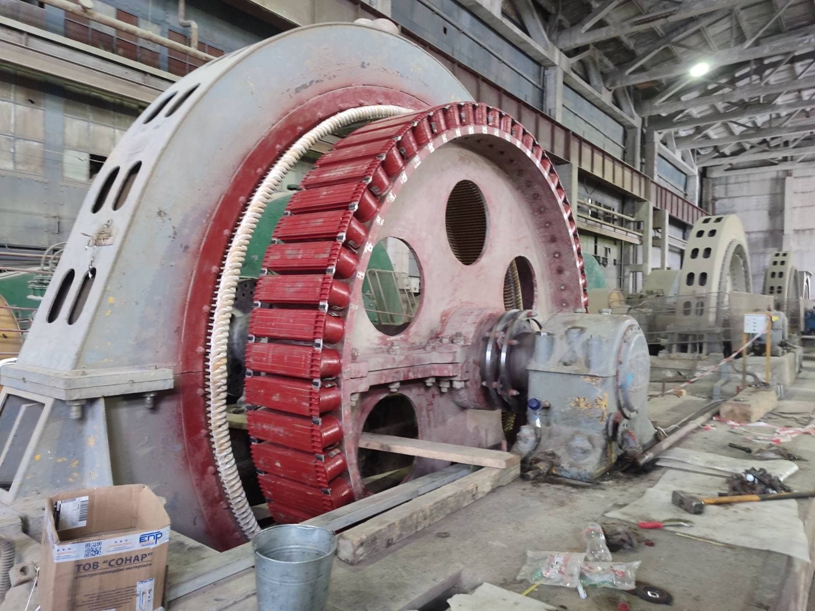
Stator and rotor windings are systems of electrical conductors placed in the stationary or rotating part of an electrical machine, designed to produce, transform, or interact with electromagnetic fields.
In different types of motors and generators, a winding can serve different functions. In the stator, it most often:
In the rotor, a winding can:
Not every rotor has a classic insulated winding, however. For example, an induction motor’s squirrel-cage rotor has a system of bars and short-circuiting rings instead of a traditional winding. That is why, when repairing an electrical machine, it’s essential to understand exactly which winding is fitted, where it sits, what function it serves, how it’s connected, what currents load it, and what insulation system is used.
The stator winding is a system of conductors in the stationary part of an electrical machine. In a three-phase motor, it usually consists of three phases and produces a rotating magnetic field. The rotor winding is a system of conductors in the machine’s rotating part. It can be a three-phase wound-rotor winding, a field winding, a damper system, or another special winding.
A winding consists of:
Its characteristics determine the machine’s electromagnetic parameters, current, voltage, torque, heating, starting properties, efficiency, and operating regime.
In the simplest sense, a winding is a system of conductors arranged and electrically connected in a specific way. But an industrial winding is a far more complex construction, one that must simultaneously provide the required electromagnetic effect, a specified electrical resistance, the necessary inductance, dielectric strength, mechanical stability, heat removal, vibration resistance, and long service life. A winding is therefore not just "copper wire" — it is a complete electromechanical and insulation system.
These terms are often used interchangeably, though technically they describe different levels of construction:
It is correct to speak of a stator section, a stator coil, or a stator winding, but these are not fully identical concepts.
The stator winding sits in the stator core’s slots. In most three-phase motors, it connects to an AC supply. Currents in its phases produce a rotating magnetic field, which interacts with the rotor and creates electromagnetic torque.
A typical layout: core → slot insulation → coil or section → slot wedge. Beyond the core, conductors transition into the winding’s end-turns, where slot-to-slot transitions, inter-coil connections, phase connections, and terminal formation happen.
In most industrial motors, the winding has three phases — U, V, and W, with terminals often labeled U1/U2, V1/V2, W1/W2. The phases are arranged in the slots so that, under three-phase supply, they produce a rotating magnetic field. It is precisely the correct spatial arrangement of the phases and the correct connection order that set the field’s direction of rotation.
Three-phase currents are offset from each other in time, and the phase windings are offset from each other in space. Combining this spatial offset with the current’s phase offset produces a resultant magnetic field that rotates around the machine’s axis — the fundamental operating principle of most three-phase motors.
A winding can form 2, 4, 6, 8, 10, 12, or more poles. The pole count directly affects synchronous speed: at the same frequency, fewer poles give a higher speed, and more poles give a lower speed. Rewinding with an arbitrary scheme change can therefore fundamentally alter the motor’s characteristics.
The magnetic field’s speed is given by:
nₛ = 120f / p
| Number of poles | Synchronous speed (50 Hz) |
|---|---|
| 2 | 3000 rpm |
| 4 | 1500 rpm |
| 6 | 1000 rpm |
| 8 | 750 rpm |
An induction rotor in motoring mode runs slightly slower. The winding scheme is set not just by pole count but also by slot count, phase count, layer count, pitch, and the number of parallel paths. A phasing error in even one coil group can cause elevated current, noise, vibration, overheating, and reduced torque.
Winding pitch determines which slots a given coil connects — it can be full, short, or specially optimized. Pitch shortening is used to reduce specific harmonics, improve the magnetic field’s shape, reduce noise, and optimize electromagnetic characteristics. Pitch is therefore not an arbitrary geometric value.
In a single-layer winding, one slot holds one coil side from a single layer — a relatively simple scheme, using fewer coils in some designs. In a double-layer winding, a slot holds two sides from different coils: one in the upper layer, one in the lower. This scheme is widely used in industrial machines and allows more flexibility in shaping pitch, distribution, phase groups, and electromagnetic characteristics.
In a distributed winding, one phase’s conductors are spread across several adjacent slots, which brings the magnetomotive force’s shape closer to sinusoidal and reduces unwanted harmonics — distributed windings are typical of many standard induction and synchronous machines. In a concentrated winding, coils for a given pole or tooth sit more locally; such designs are widely used in special motors, permanent-magnet machines, servo drives, and other compact electrical machines.
A random-wound stator winding is typical of many low-voltage motors of small and medium power. Coils are wound from round enamel-coated wire, sometimes profiled wire, and inserted into the slots after forming; slot insulation is fitted between the conductors and the core.
High-power and high-voltage machines use pre-formed coils or sections with precise geometry, length, slot section, end-turn shape, and insulation system — a coil can be fully insulated and tested before it’s inserted.
For 3 kV, 6 kV, 10 kV, and other voltage classes, insulation requirements are far higher. The system can include turn insulation, mica materials, ground-wall insulation, a semiconducting slot layer, stress-grading protection, and special impregnation. The main goal is to control the electric field and prevent local discharges.
The term "rotor winding" can refer to several fundamentally different constructions: the wound rotor’s three-phase winding, a synchronous machine’s field winding, a turbogenerator rotor’s field winding, or a salient-pole machine’s pole coils. A squirrel-cage also serves as the rotor’s electrical circuit, but structurally it is not an ordinary insulated winding.
In a wound-rotor induction motor, the rotor has a three-phase winding located in the rotor slots and, in principle, similar to the stator winding. However, it operates under harder mechanical conditions because it rotates with the rotor — it is subject to centrifugal forces, starting currents, vibration, and thermal cycling. The phases are usually connected in a star, with the three free ends brought out to slip rings; an external rheostat can be connected through brushes, allowing the rotor circuit’s resistance to be varied during starting.
Both principles (squirrel-cage and wound rotor) use current induced by the stator field. A squirrel-cage rotor has no external electrical terminals, has bars short-circuited by rings, and is simpler and more reliable. A wound rotor has an insulated three-phase winding and slip rings, allowing the rotor circuit to be influenced from outside.
In a synchronous machine, the rotor can have a DC winding — the field winding — which produces the rotor’s own magnetic field. Current reaches it through slip rings, from a brushless excitation system, or from a static system through the appropriate exciter.
In salient-pole synchronous machines, the field winding consists of individual pole coils, each of which must precisely match the required turn count, resistance, geometry, winding direction, insulation, and allowable current — a polarity error in a single coil disrupts the magnetic system of the entire machine.
In turbogenerators, the field winding sits in the slots of a massive rotor. Because of the high speed, it must have an extremely reliable mechanical fastening — slot wedges, spacer elements, end retaining rings, and special insulation are all used.
In a squirrel-cage rotor, the electrical circuit is formed by the bars and short-circuiting rings. Although no individual bar is a classic insulated turn, the whole cage functions as the induction motor’s secondary winding — current in it arises through electromagnetic induction.
Copper is the main winding material, thanks to its high conductivity, workability, mechanical ductility, suitability for soldering and welding, and thermal conductivity. Some machines use aluminum wire, an aluminum squirrel-cage, or special copper alloys.
Round wire is the most common choice for low-voltage motors, random-wound windings, and small- to medium-power machines — its typical insulation is enamel. Rectangular wire is used where slot fill needs to be higher, large currents must be handled, and precise coil forming is required — typical of high-power motors, generators, wound rotors, traction machines, and form-wound sections.
At high current, one turn can consist of several parallel conductors — this achieves the required total cross-section, eases coil forming, and helps control stray losses. In large machines, the relative arrangement of parallel conductors can matter a great deal.
A common rewinding mistake is assuming that thicker wire always makes for a better motor. That’s wrong: changing the cross-section affects resistance, current loading, slot fill, heat transfer, coil geometry, and turn count. If the turn count is changed at the same time, the machine’s entire electromagnetic regime changes.
Turn count is one of the key parameters, affecting magnetomotive force, inductance, EMF, current, and magnetic flux. An error of even a few turns can, in certain designs, cause asymmetry between phases.
A winding can have one or several parallel paths, whose purpose is to distribute current, provide the necessary cross-section, and optimize the design. All parallel paths must be as symmetrical as possible in turn count, resistance, inductance, and connections.
In a star connection, the phases join at a common neutral point, and phase voltage is lower than line voltage — this scheme is widely used in motors and generators. In a delta connection, the end of one phase joins the start of another, forming a closed loop of three phases, and line voltage is applied directly across each phase winding.
For some motors designed for the corresponding voltage, a star → run-up → delta start is used to reduce starting current. But the motor must be specifically suited to such a connection, based on its winding and supply parameters.
Insulation is just as important a part of a winding as the copper itself. Without proper insulation, the conductors cannot function as separate turns, coils, and phases.
End-turns are the parts of the coils outside the core’s slots that provide the electrical connection between slot sides. They are subject to electrodynamic forces, vibration, and thermal expansion, and during a short circuit the forces can be especially severe.
End-turn bracing uses tape, glass tape, cord ties, support rings, spacer blocks, glass-laminate elements, and special composite parts — the main goal is preventing the winding from moving.
Slot wedges hold coils or bars in the slots. Loosened wedges can lead to winding movement, insulation abrasion, vibration, conductor damage, and a ground fault.
After insertion, a winding can be impregnated with a varnish or resin. Impregnation bonds the conductors together, fills voids, reduces mechanical movement, protects against moisture, improves thermal contact, and increases dielectric strength.
In vacuum impregnation, the winding is placed under vacuum to remove air from the voids, after which the impregnating material is introduced — this helps ensure more complete penetration into the winding’s structure.
VPI (Vacuum Pressure Impregnation) uses vacuum, the impregnating material, excess pressure, and subsequent curing. The technology is widely used in high-power industrial electrical machines.
A winding operates at an elevated temperature, so its insulation materials are combined into a system of the corresponding thermal class — common classes are B and F.
A system’s class is not determined by a single material. A winding cannot be turned into class H simply by using one class-H tape or varnish if the other elements don’t match the system.
Current flowing through a conductor produces losses of P = I²R. The greater the current, the faster copper losses rise — for example, if current doubles, resistive losses at the same resistance rise roughly fourfold. Overload is therefore very dangerous for a winding.
Besides ordinary I²R losses, there can be eddy currents in the conductors, circulating currents between parallel conductors, harmonic losses, and losses from inverter supply — in large machines these can be substantial.
Modern motors often run from a variable-frequency drive. The inverter’s output voltage is not an ideal sine wave — it consists of pulses with steep edges, which can increase the stress on turn insulation, the first turns, terminals, and ground-wall insulation.
For a wound rotor:
For a synchronous rotor:
Occurs when insulation between two turns breaks down — they become electrically shorted, and a significant current can flow in the closed loop. Consequences: local overheating, asymmetry, reduced torque, rapid insulation breakdown, and progression into a phase-to-phase fault or ground fault.
At an early stage, the motor can keep running, but local heating accelerates the aging of neighboring turns — as a result, a small defect can quickly turn into a major failure.
A megohmmeter does not always detect an interturn fault. It measures insulation resistance between the winding and the frame, and between separate electrical parts. If adjacent turns short together but the whole coil is still insulated from the frame, a megohmmeter can show a normal result.
A phase-to-phase fault occurs between conductors of different phases, caused by overheating, vibration, mechanical movement, damaged phase insulation, aging, or contamination, and often causes serious winding damage.
A ground fault occurs when a live part makes electrical contact with the core or frame, due to damaged slot insulation, mechanical abrasion, aging, moisture, or an electrical discharge. The core can also be damaged at the fault location.
A broken conductor can occur in the end-turn, in the slot, at a solder joint, in a terminal, or in a parallel path — signs: resistance asymmetry, uneven currents, reduced torque, and local overheating of the other paths.
A lost phase can originate either inside the winding or in the external circuit. A motor can keep rotating after losing one phase, but currents in the remaining phases rise significantly, which can overheat the winding very quickly.
Prolonged current above the allowable level (overload) causes accelerated thermal aging — the cause can be excessive mechanical load, jamming, low voltage, frequent starts, mechanism problems, or an incorrect converter regime. A burned-out winding therefore doesn’t always mean the problem originated in the motor itself.
Contamination (dust, oil, carbon dust, metal dust, process byproducts) can degrade cooling, lower surface resistance, retain moisture, and cause electrical tracking. Moisture ingress lowers insulation resistance due to prolonged storage, condensation, water ingress, operation in a humid environment, or a cooler fault — in some cases, proper cleaning and drying can restore the winding’s parameters.
Insulation is simultaneously affected by temperature, the electric field, mechanical vibration, and the environment, so its aging is a compound process. Temperature is one of the main factors accelerating it.
The test package can include:
The exact set depends on the machine type, voltage, condition, and repair scope.
During visual inspection, look at insulation color, blackening, cracks, varnish condition, dust, moisture, discharge marks, coil movement, bracing condition, terminals, and solder joints. Visual signs often distinguish even overheating, a localized electrical failure, mechanical damage, and contamination from one another.
Insulation resistance is checked phase-to-frame, phase-to-phase, and for the rotor winding relative to the shaft or core — the value must be assessed accounting for temperature, humidity, voltage, and machine type.
The polarization index is used to assess how the insulation behaves over the time a DC test voltage is applied, and can help with analyzing moisture, contamination, and overall insulation condition, but it is also not a universal test that determines every defect on its own.
DC resistance is measured to compare phases, parallel paths, pole coils, and rotor windings, accounting for copper temperature — asymmetry can indicate an open circuit, poor contact, an incorrect scheme, or a differing turn count.
A surge test is one of the most effective methods for finding interturn weakness: a pulse is applied to the winding, its electrical response is then analyzed, and phases, identical coils, and reference results are compared.
A hipot test checks the strength of the main insulation — performed after manufacturing, after rewinding, after individual repairs, or under a scheduled program; for old insulation, the test level must be justified.
For high-voltage machines, partial-discharge measurement can be used, assessing the activity of local electrical discharges inside or on the surface of the insulation — especially relevant for large motors, generators, and high-voltage sections.
Thermal-imaging diagnostics helps identify uneven heating, defective connections, phase asymmetry, and localized problems, but temperature depends on load and ventilation, so comparable conditions are needed for a correct comparison.
A typical stator rewinding process:
Rewinding a wound rotor follows a similar process, but rotation must be accounted for — mechanical bracing, bandages, slot wedges, slip rings, and balancing are all especially important. After rewinding a rotor, dynamic balancing can be a mandatory step.
Manufacturing a stator section includes:
For high-voltage sections, the process is significantly more complex.
Required:
It’s best to also have drawings, factory data, the old winding, and photos taken before disassembly.
In many cases, a winding can be reproduced without drawings: pitch, turn count, cross-section, phasing, scheme, and geometry can all be determined from the existing winding. But there is an important risk — the old winding may have already been rewound incorrectly in the past, so its parameters should be verified by calculation and against the motor’s nameplate data.
In some cases, a winding can be upgraded: switching to a different voltage, changing the frequency, adapting it for a converter, raising the insulation class, or modernizing the impregnation process. But any winding change must account for magnetic saturation, current loading, heating, slot space, mechanical strength, and cooling — simply "adding more copper" is not enough.
If a new winding fails quickly, the cause can be incorrect winding data, a damaged core, overload, faulty mechanics, insufficient cooling, supply asymmetry, an incorrect converter, poor insulation quality, or mechanical winding movement. A good repair is therefore more than just rewinding.
What not to do:
A winding must be treated as a system: copper + insulation + scheme + mechanical bracing + impregnation + cooling. Checking electrical resistance alone can miss mechanical movement, local weakness, cracks, and bracing damage. Checking with a megohmmeter alone can miss an interturn defect, an open parallel path, or an incorrect connection.
The winding can look like it simply "overheated." But the heating pattern across the phases often points to an asymmetric condition. Check the supply, the contactor, the cable, the terminals, and the protection. Fixing only the motor can let the defect recur.
Possible causes: fewer turns, an incorrect scheme, an incorrect pitch, core damage, a connection error, or a mechanical issue. The new data must be compared against the nameplate specifications.
Check DC resistance, turn count, parallel paths, contact connections, phase current, and interturn condition.
Possible causes: incorrect phasing, an interturn fault, an incorrect pitch, air-gap asymmetry, or a rotor problem. High insulation resistance does not confirm the electromagnetic scheme is correct.
This can mean the main cause was moisture. But before returning the motor to service, check why moisture got in, whether there’s contamination, the insulation’s condition, the terminals, and the cooling system.
| Symptom | Possible cause | What to check |
|---|---|---|
| Low insulation resistance | Moisture or contamination | Cleaning, drying |
| Good insulation, but overheating | An interturn fault | A surge test |
| One phase has different resistance | An open path or connection | DC resistance |
| The motor hums after rewinding | A scheme error | Phasing and pitch |
| No-load current is elevated | Too few turns | The winding data |
| The winding moves | Loosened wedges | The slot bracing |
| Dust near the end-turns | Mechanical rubbing | The bracing |
| Local blackening | Overheating or a discharge | The coil and connections |
| Uneven phase heating | Asymmetry | Currents and resistances |
| The rotor winding overheats | The starting regime | The rheostat and contacts |
| Sparking at the rings | Brushes or the surface | The slip rings |
| Frequent breakdowns after a repair | The insulation system | Materials and process |
A system of electrically connected conductors in the stator that produces a magnetic field or draws electrical power in generator mode.
A system of conductors in the machine’s rotating part. It can be a wound-rotor winding or serve as a field winding.
Functionally, it acts as the rotor’s secondary electrical circuit, though structurally it consists of bars and rings rather than insulated coils.
A turn is one closed electrical loop of a conductor. A coil is one or more turns formed into a specific geometry. A section is an individual structural winding element prepared for installation in the machine.
Because of its high conductivity, thermal conductivity, and workability.
Due to overload, a lost phase, interturn defects, cooling problems, aging, or mechanical damage.
Not always — it assesses insulation resistance to the frame, not the insulation between adjacent turns of the same coil.
For mechanical reinforcement, moisture protection, and improved heat removal.
In many designs, yes, if the technical condition of the rest of the winding allows a local repair.
Only after a technical calculation — changing the cross-section or the turn count affects the machine’s entire electromagnetic regime.
So a new winding isn’t installed into a magnetic system that has a defect and local overheating.
If the root cause isn’t addressed: overload, a supply fault, a mechanical defect, ventilation problems, or core damage.
Electropromremont LLC manufactures, repairs, rewinds, and restores windings for electrical machines.
Depending on the equipment type, the following can be performed:
Whether a specific winding can be repaired or manufactured is determined after analyzing the electrical machine’s design, voltage, power, conductor type, winding data, insulation system, and technical condition.
Stator and rotor windings are among the most important elements of an electrical machine. It is the windings that form the electromagnetic system responsible for producing the magnetic field, transferring energy, generating torque, and producing electrical voltage.
A winding is not just copper wire, however — it includes a scheme + conductors + turns + coils + insulation + mechanical bracing + connections + impregnation.
The quality of a rewind is determined not by how much new copper goes in, but by how precisely the electromagnetic scheme is reproduced, the quality of the insulation system, and the mechanical stability of the whole winding.
Professional rewinding should therefore include:
This material is for informational purposes. The values, diagnostic methods, scope of work and recommendations given here are general and do not replace the manufacturer’s technical documentation. The final decision for a specific machine is made from its own diagnostics and inspection, taking into account its type, power, design, duty, operating history and applicable standards.
We handle winding defect inspection, insulation-resistance and interturn diagnostics, manufacture of sections and coils, stator or wound-rotor rewinding, and final acceptance testing.