What is a motor stator?
The stator is the stationary part of a motor, containing the magnetic system and, in most AC motors, the working winding.
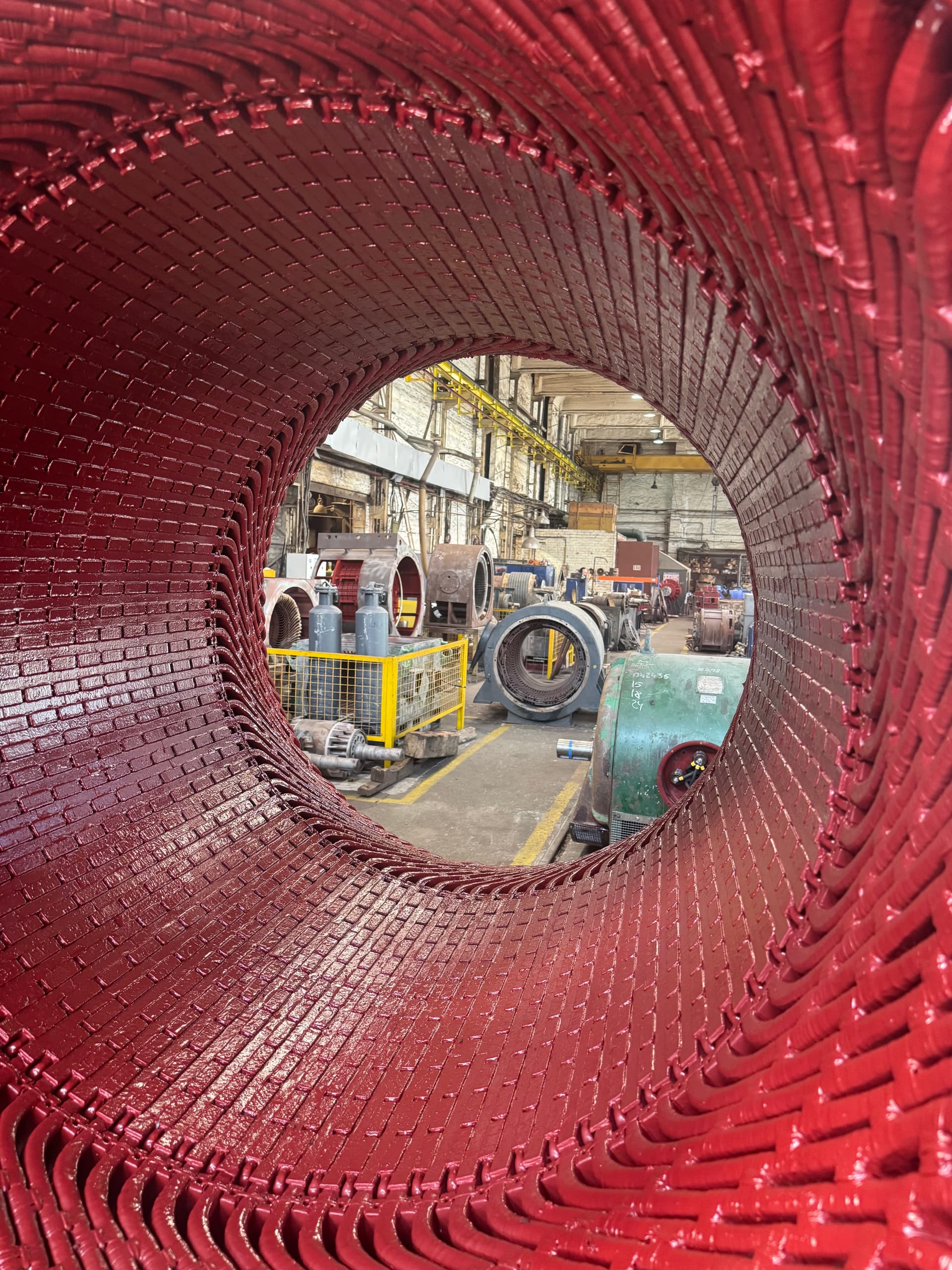
A motor stator is the stationary part of an electrical machine that, together with the rotor, forms its electromagnetic system. In most AC motors, the working winding sits in the stator; when current flows through it, it produces a magnetic field. This field interacts with the rotor to produce electromagnetic torque.
A stator is used in:
Stator design depends on power, voltage, rotational speed, cooling method, and the machine’s purpose. The stator of a small low-voltage motor and the stator of a high-voltage machine rated at several megawatts can differ fundamentally in winding design and insulation system, even though they perform the same basic function.
The stator is the stationary part of a motor or generator, usually consisting of:
The stator’s main job is to produce the magnetic field needed for electromagnetic torque. In a generator, the energy-conversion principle runs the other way: the rotor’s electromagnetic field interacts with the stator winding, inducing an electrical voltage in it.
The stator surrounds the rotor and stays stationary while the machine runs. In simplified form, the construction can be represented as:
frame → stator core → slots → winding → air gap → rotor
The air gap sits between the stator’s inner surface and the rotor’s outer surface. Its size is an important parameter of the electrical machine. An excessive or non-uniform air gap can affect magnetic flux, current, efficiency, reactive power, vibration, noise, heating, and electromagnetic forces.
Construction depends on the machine type, but the main elements are:
The frame can be made of cast iron, steel, a welded steel structure, an aluminum alloy, or special constructions for high-power machines.
The frame performs several functions: it holds the core, provides geometric rigidity, carries mechanical loads, serves as a base for the bearing brackets, participates in heat removal, and protects the internal parts.
In large electrical machines, the frame can be a complex welded structure with stiffening ribs, ventilation ducts, cooling chambers, support elements, inspection hatches, and sensor mounts.
The core is part of the motor’s magnetic system. It is not made from a solid piece of steel, but is usually built up from a large number of thin electrical-steel laminations. Each lamination has an insulating coating that limits eddy currents between laminations. This reduces eddy currents, iron losses, local heating, and the machine’s overall losses.
As the motor runs, the magnetic field changes over time. If the core were made from a solid mass of electrically conductive steel, significant eddy currents would arise in it, causing extra energy losses, strong heating, and reduced efficiency. That is why the core is laminated from thin sheets, electrically insulated from one another.
The core includes the back-iron, teeth, slots, ventilation ducts, and pressure elements. The stator teeth sit between the slots and carry magnetic flux to the air gap. The core back-iron closes the magnetic flux between pole zones.
The winding sits in the core’s slots. Slots can be open, semi-closed, semi-open, closed, rectangular, or specially shaped. Slot design depends on the winding type, voltage, power, conductor size, coil-insertion method, and the required magnetic regime. Large high-voltage machines often use open or semi-open slots, which allow pre-formed, pre-insulated coil sections to be fitted.
The stator winding is a system of electrically connected conductors or coils placed in the core’s slots. In a three-phase motor, it usually consists of three phases. Once connected to a three-phase supply, the currents in the windings create a rotating magnetic field, which interacts with the rotor and produces torque.
These terms are often used interchangeably, but technically they don’t always mean the same thing. The stator winding is the complete system of conductors for all stator phases. A stator coil is an individual structural element of the winding with one or more turns. A stator section (or bar) is a term often used for an individual pre-formed winding element, especially in large electrical machines.
When searching for spare parts in practice, customers may use any of these terms: stator coil, stator section, stator winding, stator bar, or winding section. A technical catalog should therefore use these terms together, without presenting them as fully identical concepts.
Depending on the machine design, the following are used:
The choice depends on power, voltage, pole count, slot count, connection scheme, cooling method, and manufacturing technology.
A random-wound winding is typical for many low-voltage motors of small and medium power. Conductors are inserted into the slots as the winding is formed, usually using insulated round or profiled magnet wire. Advantages: relatively simple technology, lower cost, and suitability for machine winding. For large high-voltage motors, this design is often unsuitable because of geometry and dielectric-strength requirements.
Pre-manufactured sections are used for high-power and high-voltage machines. A typical process includes selecting the conductor, winding, forming the geometry, applying turn insulation, forming the ground-wall insulation, pressing or heat-treating (depending on the system), dimensional checks, electrical testing, inserting into the slots, connecting the sections, bracing the end-turns, and impregnation or another specified process.
Windings are mostly made with copper magnet wire — round, rectangular, profiled, enamel-coated, taped, glass-fiber insulated, or with a combined insulation system. In large machines, one section can consist of several parallel conductors; certain designs use conductor transposition to reduce stray losses.
When manufacturing or rewinding, it is essential to know the exact slot, pole, and phase counts, the winding pitch, turn count, number of parallel paths, conductor cross-section, winding direction, phase sequence, connection scheme, and terminal layout. Changing even one parameter can change the motor’s characteristics.
A three-phase winding can be connected in a star (Y) or delta (Δ) scheme. In a star connection, the three phase ends join at a common point; in a delta connection, the phases form a closed loop in series. The scheme is set by the motor’s design and its rated data — it must never be changed arbitrarily without analyzing the winding and the supply parameters.
The parts of the coils that extend beyond the core are called end-turns (end-windings). They are not held in slots, so they need separate mechanical bracing. They are subject to electrodynamic forces, vibration, thermal expansion, starting forces, and short-circuit forces. In large machines, end-turn bracing is one of the critical design elements.
Bracing tape, glass tape, cord ties, support rings, spacer blocks, insulating blocks, glass-laminate parts, composite materials, and special brackets can all be used. The goal is to prevent the winding from shifting under electromagnetic and mechanical forces.
The insulation system is one of the stator’s most important parts. It must provide dielectric strength between turns, between coils, between phases, between the winding and the core, and between live parts and the frame. At the same time, the insulation must withstand temperature, vibration, electrodynamic forces, moisture, contamination, thermal cycling, and surge overvoltages.
A design can use:
Electrical machines use insulation systems of various thermal classes — commonly B and F. An insulation system’s class describes its allowable thermal level under the applicable requirements.
A common mistake is assuming that a class designation — say, F — automatically means every point in the motor may run at the class’s limiting temperature. The actual allowable heating also depends on ambient temperature, the measurement method, machine design, thermal margin, operating conditions, and manufacturer requirements.
Modern high-power machines widely use thermosetting insulation systems. After curing, they form a rigid structure with high mechanical strength, good thermal stability, vibration resistance, geometric stability, and high dielectric strength. High-voltage sections can use systems based on mica, glass fabric, epoxy binders, or composite materials.
Thermoplastic systems can soften and change their mechanical properties on heating. Such systems are typical of a number of older machine designs. During repair, it is important to correctly identify the original insulation type, since the technology for removal, repair, and restoration can differ substantially.
Once the winding is fitted in a slot, it must be securely held in place. Slot wedges do this job and can be made of glass-laminate, laminate (textolite), specially treated wood in older designs, composite materials, or magnetic wedges. A wedge must provide mechanical retention, winding stability, vibration resistance, and the required dielectric properties.
Some machines use magnetic or semi-magnetic wedges. Their use can affect the slot zone’s magnetic reluctance, field harmonics, noise, no-load current, and electromagnetic losses — so a magnetic wedge should never be replaced with an ordinary glass-laminate one without an engineering calculation.
After the winding is inserted, it can be impregnated with an insulating varnish or resin compound. The main goals of impregnation: filling voids, fixing the conductors in place, increasing mechanical strength, protecting against moisture, improving heat transfer, reducing vibration, and extending service life.
Vacuum removes air and some of the moisture from the winding’s voids before the impregnating material is introduced, allowing the varnish or resin to penetrate more deeply. This technology can be used when manufacturing a new winding, rewinding, performing a major overhaul, or restoring certain insulation systems.
VPI (Vacuum Pressure Impregnation) is a vacuum-and-pressure impregnation process. A typical cycle can include pre-drying, evacuation, feeding the impregnating material, a soak period, applying excess pressure, draining the material, and curing. Specific parameters are set by the materials and the process documentation.
A stator generates significant heat from copper losses, iron losses, additional electromagnetic losses, and high-frequency components under converter supply. Heat is removed using external air cooling, internal ventilation, independent ventilation, heat exchangers, water cooling, or combined systems. In large machines, the core can have radial ventilation ducts.
High-power motors and generators can have temperature sensors embedded in the stator — Pt100, thermocouples, PTC sensors, and other types. They monitor winding temperature, core temperature, cooling-air temperature, and sometimes specific zones. This data is used for alarms, emergency protection, operating-mode analysis, and condition forecasting.
In a three-phase induction motor, the stator produces a rotating magnetic field whose speed is set by supply frequency and pole count. The rotor turns slightly slower than the stator field — this difference is what induces current in a squirrel-cage or wound rotor. An induction machine’s stator can have a low-voltage random-wound winding, a form-wound coil winding, or high-voltage sections.
In a synchronous motor, the stator also produces a rotating magnetic field. The rotor has its own magnetic field, produced by a field winding or permanent magnets. In steady synchronous operation, the rotor turns in synchronism with the stator field. For high-power synchronous machines, insulation dielectric strength, mechanical bracing of the sections, core condition, air-gap uniformity, and the cooling system are all especially important.
In many generators, the main power winding sits in the stator. As the rotor’s magnetic field rotates, an electrical voltage is induced in the stator winding. For large generators, the stator is one of the machine’s most complex and expensive components. Its repair can include replacing individual bars or sections, insulation and terminal repair, restoring bracing, core repair, sensor replacement, and partial or complete rewinding.
An interturn fault occurs when insulation between adjacent turns of the same coil breaks down. A closed loop of very low resistance forms, which can carry a significant circulating current and cause local heating. The process can develop very quickly: insulation damage → a shorted turn → local current → heating → destruction of adjacent insulation → a phase-to-phase fault or a ground fault. Early detection of an interturn defect is therefore very important.
A megohmmeter mostly assesses winding-to-ground and phase-to-phase insulation resistance. If two adjacent turns of the same coil short together, the insulation of the entire winding to ground can still remain adequate. A motor can therefore have good insulation resistance and an interturn defect at the same time — other methods are used to find it.
A phase-to-phase fault occurs between the live parts of different phases, caused by damaged phase insulation, end-turn displacement, overheating, contamination, moisture, mechanical damage, or a developing interturn defect. It is often catastrophic and can cause significant damage to the winding and core.
A winding ground fault is a breakdown of insulation between a live part and the grounded core or frame. Typical causes: insulation aging, overheating, mechanical abrasion, damaged slot insulation, moisture, contamination, partial discharges, and surge overvoltages. An electrical arc at the fault point can damage not only the winding but also the core laminations.
A loosened wedge lets the winding shift within the slot, which can lead to vibration, insulation abrasion, breakdown of the impregnation, conductive dust, coil damage, and a ground fault. For large machines, checking the slot bracing is an important part of the inspection.
End-turn damage arises from electrodynamic forces, frequent starts, short circuits, vibration, loosened bracing, material aging, or an improper repair. Signs: cracked varnish, abrasion dust, movement marks, loosened cord ties, cracked insulation, deformation, and local heating.
The core can develop interlaminar shorts, melting, dents, tooth damage, loosened pressing, corrosion, local overheating, and rotor-rub marks. Damage to the interlaminar insulation is especially dangerous — eddy currents rise at that spot and cause local heating, which can damage a new winding again after a rewind.
If the air gap is disturbed, the rotor can touch the stator’s inner surface. Causes: bearing damage, a bent shaft, frame deformation, incorrect assembly, eccentricity, core displacement, or a loosened bearing bracket. Consequences: tooth damage, shorted laminations, winding destruction, heating, vibration, and rotor damage.
Diagnostics should be comprehensive. Depending on design and condition, these methods can be used:
A single test does not give a complete picture of a stator’s condition.
During inspection, look at insulation color, overheating marks, cracks, delamination, dust, oil, moisture, signs of electrical discharge, the condition of the wedges and bracing, end-turn position, terminal condition, local burn marks, and rotor-rub marks. An experienced inspection often points to the direction of further diagnostics before any electrical testing.
Insulation resistance is measured between phases, between each phase and the frame, and for the whole winding to ground. The result depends on temperature and humidity, so comparing measurements without accounting for conditions is not valid. Low resistance can result from moisture, contamination, aging, damage, or conductive dust. Sometimes cleaning and drying substantially restore the readings, but that does not automatically rule out other defects.
Phase resistances are compared with each other, accounting for winding temperature. A deviation can indicate a poor connection, an open parallel path, a wiring error, a terminal defect, or damage to part of the winding. Low-resistance windings need an appropriate measuring instrument, since contact and lead resistance can be comparable to the measured value.
A surge test is used to find interturn-insulation defects — the response of different phases, similar coils, and reference characteristics is compared. Interturn-insulation damage changes the winding’s electrical parameters, which shows up in the pulse waveform.
After removing the old winding, it is important to check the core before installing the new one — otherwise a new winding can end up in a core with a local defect that will cause overheating again. Tooth condition, interlaminar insulation, pressing tightness, rub marks, local melting, gouges, corrosion, and mechanical damage are all checked.
One method for a thermal core test involves creating a magnetic flux in the core and monitoring the temperature field — areas with damaged interlaminar insulation can run hotter. Temperature sensors, thermal imaging, or specialized core-diagnostic systems are used for monitoring. The method and flux level must match the machine’s design and the process documentation.
A complete rewind can be necessary for:
But rewinding should not be an automatic response to every defect. Sometimes cleaning, drying, terminal repair, restoring bracing, replacing a single section, re-wedging, local insulation repair, or re-impregnation is enough — if the technology allows it.
A typical rewind process includes:
The exact process depends on the machine design. Before disassembly, the scheme, turn count, pitch, conductor cross-section, number of parallel paths, phase layout, connection type, coil geometry, end-turn length, and terminal position must all be recorded. This is especially important for old motors, where the original design documentation may be unavailable — but copying the old winding without verification is also risky, since the machine may have already been repaired incorrectly in the past.
The term "manufacturing a stator" can cover different scopes of work: manufacturing a wound stator (using the existing frame and core but making a new winding), manufacturing a core (making a new electrical-steel stack), or fully manufacturing a stator (frame, core, pressure elements, winding, insulation, wedges, terminals, sensors, and bracing system). Replicating a stator requires restoring not just its geometry but also the original design’s electromagnetic parameters.
Manufacturing a stator core can include developing or restoring the lamination drawing, selecting the electrical-steel grade, producing the laminations or segments, applying or checking the insulating coating, stacking the pack, forming ventilation ducts, pressing, clamping the pack, machining, checking the geometry, and verifying the magnetic condition. For large machines, the core can be assembled from segments directly inside the frame.
In many cases a stator can technically be manufactured from a sample, but a single physical sample may not be enough. The geometry, steel grade or its properties, stack length, slot count, slot shape, pole count, winding scheme, turn count, conductor cross-section, insulation class, cooling system, supply parameters, and rated characteristics of the machine all need to be determined. Manufacturing a replica should therefore begin with technical analysis, not simply copying external dimensions.
A stator can be supplied as a separate assembly at various stages of completion: a frame without a core, a frame with a core, an unwound core, a wound stator, a fully complete stator with terminals, a stator with sensors, or a stator after a major overhaul. It’s therefore important, when ordering, to clarify exactly what is meant by "motor stator."
The decision between a new or a rebuilt stator depends on the condition of the frame, core, fits, winding, insulation, geometry, and economic viability. If the frame and core are in good condition, manufacturing a completely new stator is often unnecessary — manufacturing a new winding and a full restoration is enough. If the core has critical damage, it may need repair or a new stack.
What not to do:
When repairing an electrical machine, it’s important not to limit the inspection to the single question of "is the winding OK, or does it need rewinding?" A stator must be treated as a system: frame + core + winding + insulation + bracing + cooling + terminals + sensors. Replacing only the winding without fixing the root cause of its failure can let the defect recur.
After a failure, you might see a badly damaged winding and draw the obvious conclusion that a rewind is needed. But the root cause could have been bearing damage, rotor-to-stator contact, blocked ventilation, voltage asymmetry, a converter fault, frequent overloads, a loosened wedge, or a core defect. Simply rewinding the stator without finding the root cause can let the new winding fail again.
After a new winding is fitted, one zone of the stator runs hotter. Possible causes: damaged interlaminar core insulation, an incorrect connection, a coil defect, disrupted ventilation, mechanical damage during insertion, or a local impregnation defect. Checking the core before fitting a new winding is therefore fundamentally important.
High insulation resistance does not prove the winding is fully sound. Possible causes: an interturn fault, an incorrect scheme, phase asymmetry, a core defect, disrupted cooling, overload, or incorrect supply parameters. A megohmmeter is therefore an important tool, but not the only one.
The cause may not be in the stator itself. Rotor balance, bearings, the shaft, the air gap, the foundation, motor mounting, electromagnetic symmetry, core condition, and frame rigidity all need checking. Diagnostics should treat the motor as a single electromechanical system.
| Symptom | Possible cause | What to check |
|---|---|---|
| The stator overheats evenly | Overload | Current, load, cooling |
| One phase runs hot | Asymmetry or a winding defect | Phase resistance, currents |
| One zone runs hot locally | An interturn defect or the core | The winding and steel stack |
| Low insulation resistance | Moisture, contamination, aging | Cleaning, drying, insulation |
| Insulation resistance is normal, but the motor overheats | An interturn fault | Surge testing |
| The motor hums loudly | A magnetic or mechanical issue | Currents, gap, core |
| The winding shifts in the slot | Loosened wedges | The slot bracing |
| Dust near the end-turns | Mechanical rubbing | Bracing and fastenings |
| Rub marks on the core | Rotor contact | Shaft, bearings, gap |
| The core runs hot locally | An interlaminar short | A magnetic test |
| Phases have unequal resistance | A connection or winding issue | DC resistance |
| Breakdown after starting | Damaged insulation | Slot and ground-wall insulation |
| Overheating after a rewind | A winding or ventilation error | The scheme, currents, cooling |
| Elevated vibration | Eccentricity or a mechanical defect | Gap, rotor, bearings |
The stator is the stationary part of a motor, containing the magnetic system and, in most AC motors, the working winding.
In a motor, it produces the magnetic field that interacts with the rotor and creates torque.
Main parts: the frame, core, slots, winding, insulation, slot wedges, end-turns, and terminals.
To limit eddy currents and reduce losses and heating.
A section is an individual structural element of the winding, formed from a specific number of turns or conductors and intended for a specific slot. The winding is the assembly of all correspondingly connected sections or coils.
Causes can include overload, an interturn fault, a lost phase, insufficient cooling, overvoltage, mechanical damage, or insulation aging.
Yes, if the winding’s condition allows a local repair. The decision is made after diagnostics.
In many designs, yes — but the condition of the rest of the winding must be assessed, and the new section must match the original parameters.
Some designs can theoretically be upgraded, but simply changing the conductor cross-section does not automatically raise the power rating — the limits are set by the magnetic system, cooling, current loading, and mechanics.
Yes, especially if the old winding burned out or there was rotor-to-stator contact.
To mechanically fix the winding in place, protect it from moisture, fill voids, and improve heat removal.
The decision depends on why the resistance dropped and the results of other checks. Recovering one metric does not confirm the machine is fully sound.
Electropromremont LLC performs diagnostics, repair, rewinding, and restoration of electrical-machine stators, as well as manufacturing windings, coils, and stator sections for industrial motors and generators.
Depending on the equipment’s design and technical condition, the following can be performed:
Whether a specific stator can be manufactured or repaired is determined after analyzing the machine type, power, voltage, winding design, dimensions, technical condition, available documentation, and testing requirements.
The stator is one of the key components of a motor or generator. Its technical condition is not defined by the winding alone. A proper assessment must cover: frame → core → slot system → winding → insulation → bracing → terminals → cooling.
Main stator defects:
It is not enough to replace a burned-out winding — you have to determine why it failed.
A quality stator restoration includes diagnostics, a core inspection, restoring or manufacturing the winding, choosing the right insulation materials, reliable mechanical bracing, impregnation, and final electrical testing.
This material is for informational purposes. The values, diagnostic methods, scope of work and recommendations given here are general and do not replace the manufacturer’s technical documentation. The final decision for a specific machine is made from its own diagnostics and inspection, taking into account its type, power, design, duty, operating history and applicable standards.
We handle winding and core inspection, insulation-resistance measurement, local repair, or a complete stator rewind matched to your machine’s design.