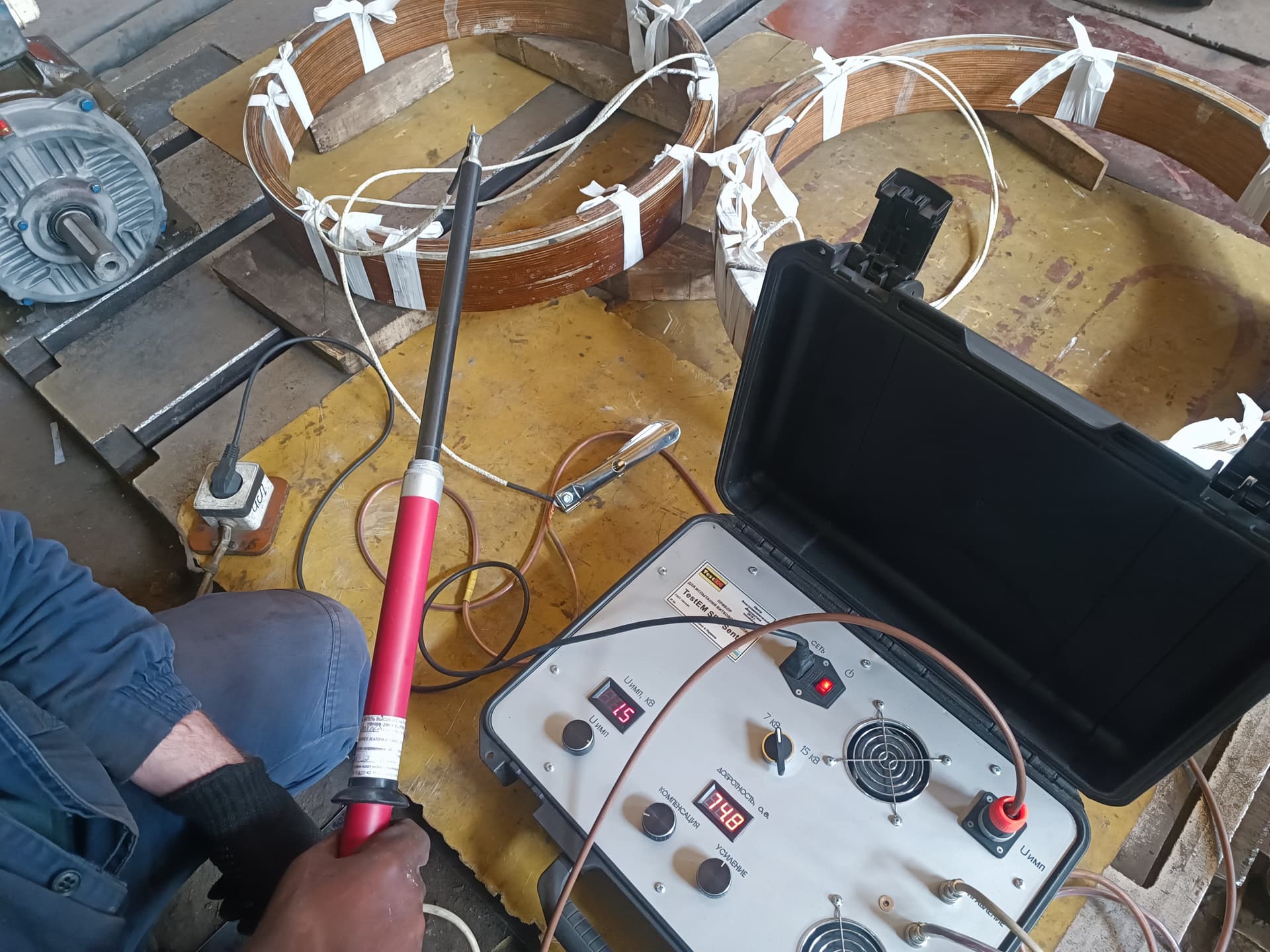
An interturn short circuit is one of the most dangerous faults that can develop in the windings of electrical machines. At an early stage the motor can keep running without tripping the protection or showing any obvious short circuit. Inside the damaged coil, however, a significant local current is already flowing, rapidly heating the conductors, destroying the insulation of neighbouring turns, and gradually turning a local defect into complete winding damage.
An interturn short circuit can occur in the stator winding, the rotor or armature winding, the field winding of a DC motor, a generator, or a transformer. Most often the cause is not a single event but a combination of thermal ageing, contamination, vibration, overvoltages, insufficient impregnation, and repair defects.
01
The short answer
An interturn short circuit appears when the insulation between two or more adjacent turns of a winding loses its dielectric strength.
The main causes are:
prolonged overheating of the winding;
ageing and drying-out of the insulating materials;
local overvoltages;
impulses from a variable frequency drive;
mechanical movement of the conductors in the slots;
vibration of the coils and the end windings;
damage to the wire enamel during winding;
insufficient or uneven impregnation;
contamination, moisture, oil, and conductive dust;
frequent starts and high starting currents;
motor overload;
uneven cooling;
partial discharges in high-voltage windings;
defects left after a repair or rewinding;
loosened winding fastening;
ageing of the insulation caused by temperature cycling.
Once the insulation breaks down, part of the turns forms a closed loop. A significant current is induced in this loop that does not fully pass through the external protective devices. Because of this, the defect can develop very quickly even if the motor’s phase current has increased only slightly.
02
What an interturn short circuit is
The winding of an electric motor is made up of conductors laid out as turns and coils. Each turn is electrically insulated from its neighbours by a layer of enamel, tape insulation, or a combined system of insulating materials.
An interturn short circuit occurs when two adjacent turns, or several turns of the same coil, come into contact with each other without the required insulating layer between them.
As a result, part of the winding is effectively removed from the normal electrical circuit. The shorted turns turn into a closed loop in which the magnetic field induces a high circulating current.
This current:
locally heats the conductors;
accelerates the breakdown of the enamel;
chars the insulation;
damages neighbouring turns;
changes the inductance of the coil;
creates asymmetry in the magnetic field;
increases the current of the damaged phase;
can cause a phase-to-phase short circuit or a breakdown to the frame.
03
How an interturn short circuit differs from other faults
Several types of winding fault need to be distinguished.
Interturn short circuit
A short circuit between the turns of a single coil or a single part of the winding.
Inter-coil short circuit
Electrical contact between different coils of the same phase.
Phase-to-phase short circuit
A breakdown of the insulation between the windings of different phases.
Short circuit to the frame
Contact between a live part of the winding and the earthed core, the frame, or another metal part.
Winding open circuit
A complete or partial break in the electrical circuit of a conductor, a connection, or a lead.
An interturn defect is often the initial stage of a more serious failure. First a few turns are damaged, then the overheated zone expands, after which a phase-to-phase short circuit or a breakdown of the winding to the frame can occur.
04
How an interturn short circuit develops
The damage process usually goes through several stages.
1. Weakening of the insulation
The insulation between the turns loses its elasticity, mechanical strength, or dielectric resistance.
The cause can be:
overheating;
ageing;
vibration;
contamination;
moisture;
an overvoltage;
a manufacturing defect.
2. Appearance of a local breakdown
A brief electrical discharge, or direct contact between conductors, occurs between two turns.
At this stage the defect may show up only during:
starting;
heating of the motor;
a sudden load;
a voltage impulse;
operation from a variable frequency drive.
3. Formation of a closed loop
The damaged turns form a loop with a very low resistance. A significant circulating current arises in it.
4. Local overheating
The current in the shorted turns causes the temperature to rise sharply. At the same time, the overall frame temperature, or even the average winding temperature, can still remain within the permissible range.
5. Spreading of the damage
The heat destroys the insulation of neighbouring conductors. The number of shorted turns increases.
6. Complete winding damage
The defect develops into:
an inter-coil short circuit;
a phase-to-phase short circuit;
a breakdown to the frame;
burning of a slot;
damage to the stator core;
tripping of the overcurrent or differential protection.
05
Main causes of an interturn short circuit
01
Prolonged overheating of the winding
Elevated temperature is one of the main causes of accelerated ageing of the insulation.
During overheating, the insulating materials:
lose their elasticity;
become brittle;
crack;
delaminate from the conductor;
lose their dielectric strength;
withstand vibration and voltage impulses less well.
What is particularly dangerous is not only a severe one-off overheating event, but also prolonged operation at a temperature that systematically exceeds the design value for the corresponding insulation class.
The causes of overheating can include:
overload;
undervoltage;
phase imbalance;
a phase open circuit;
contaminated ventilation ducts;
a faulty fan;
frequent starts;
jamming of the driven mechanism;
an incorrect operating regime;
insufficient motor power for the actual load.
02
Natural ageing of the insulation
Even under normal conditions, insulation gradually ages.
Its condition is affected by:
the length of service;
the operating temperature;
the number of starts;
temperature cycling;
humidity;
vibration;
the chemical environment;
the quality of the original manufacture.
Over time, the wire enamel and the impregnating compound can become stiff and brittle. When conductors move mechanically, micro-cracks appear that gradually turn into an electrical breakdown.
03
Frequent motor starts
During a direct-on-line start, the motor current can exceed the rated value several times over.
Every start is accompanied by:
a sharp rise in conductor temperature;
electrodynamic forces;
a mechanical jolt to the winding;
movement of the end windings;
additional stress on the interturn insulation.
If the motor is started more often than the design allows for, the insulation does not have time to cool down and mechanical stresses accumulate.
Particularly dangerous are:
prolonged starts;
starts under a heavy load;
repeated starts without a sufficient pause;
starting at a reduced voltage;
starting a mechanism that is jammed or has an increased resisting torque.
04
Voltage impulses
The interturn insulation is designed for a much smaller potential difference than the insulation between a phase and the frame. However, steep voltage impulses can be distributed unevenly across the turns.
The greatest stress often falls on the first turns of the coil, near the lead.
The sources of impulses can include:
contactor switching;
vacuum circuit breakers;
fault processes in the network;
lightning overvoltages;
incorrect earthing;
long cable runs;
operation from a variable frequency drive;
wave reflections in the cable;
high values of voltage rise rate.
A brief impulse does not always immediately cause a stable short circuit. At first it can cause a micro-breakdown, a partial discharge, or local damage to the enamel, which subsequently develops further under the effect of temperature and vibration.
05
Operation of the motor from a variable frequency drive
A variable frequency drive forms the voltage using fast semiconductor switching. Impulses with a high voltage rise rate appear at the motor terminals.
The stress on the interturn insulation increases with:
a long cable between the drive and the motor;
a high switching frequency;
the absence of an output choke;
the absence of a dU/dt filter or a sine-wave filter;
an incorrectly chosen cable;
poor earthing;
the use of an old motor not designed for inverter supply.
In practice, a motor can run from the mains for years without obvious problems, but once it is connected to a frequency converter, weakened insulation can break down quickly.
06
Mechanical movement of conductors in the slot
Electromagnetic forces act on the winding; they vary with the current frequency and depend on the motor load.
If the coils are not adequately secured, the conductors can:
vibrate;
rub against each other;
move relative to the slot insulation;
strike the wedges;
damage the enamel;
deform under starting currents.
The causes of this movement can include:
loosened slot wedges;
shrinkage of the impregnating material;
insufficient tightness of the winding layout;
incorrect wedging;
ageing of the bandages;
weak fastening of the end windings;
electrodynamic shocks during short circuits.
Mechanical wearing of the insulation is particularly dangerous because the defect can be local and undetectable in an ordinary insulation resistance measurement.
07
Vibration of the end windings
The end windings of the coils are located outside the slots and are subjected to significant electrodynamic forces.
If the fastening loosens, they can:
oscillate;
rub against each other;
come into contact with metal parts;
damage the spacers;
wear through the interturn or inter-coil insulation.
Possible signs include:
white or black dust in the area of the end windings;
traces of rubbing;
loosened bandages;
cracks in the impregnating varnish;
a characteristic noise;
local traces of overheating.
08
Damage to the wire during winding
An interturn defect can already be introduced during the manufacture or rewinding of the winding.
Typical causes include:
excessive wire tension;
a sharp bend;
contact with a sharp edge;
a damaged guide roller;
contaminated winding equipment;
dropping the coil;
incorrect forming;
impacts on the conductors;
the use of tools with sharp edges;
pulling the wire through damaged tooling.
In this case the enamel can be partially damaged, but contact between conductors will only occur after impregnation, drying, insertion into the slot, or several heating cycles.
09
Damage to the winding during insertion into the slots
Even a correctly wound coil can be damaged during installation.
The following are hazardous:
sharp slot edges;
burrs on the core;
damaged slot insulation;
excessive compaction;
hammer blows without protective tooling;
an incorrectly sized coil;
twisting of the conductors;
pulling the coil through with excessive force;
damage during the installation of the wedges.
Particular attention must be paid to the point where the conductors exit the slot, where mechanical stress, vibration, and the electric field all act at the same time.
10
Insufficient impregnation of the winding
The impregnating material performs several functions:
secures the conductors;
fills air voids;
improves heat transfer;
protects against moisture;
reduces vibration;
increases the dielectric strength of the insulation system.
If impregnation is insufficient, voids remain inside the winding. Conductors can move, and partial discharges can occur in the voids of high-voltage windings.
The causes of poor-quality impregnation include:
unsuitable varnish viscosity;
insufficient dwell time;
incorrect temperature;
a contaminated winding;
residual moisture;
a disrupted vacuum cycle;
insufficient pressure;
an incorrect curing regime;
incompatibility of materials;
re-use of a degraded impregnating compound.
11
Voids and defects in the insulation system
The following can remain within the thickness of the insulation:
air inclusions;
unimpregnated areas;
folds in the tape;
delamination;
cracks;
foreign particles;
incorrect overlap of the insulation layers.
In high-voltage machines, such defects create zones of elevated electric field strength. Partial discharges can occur in them, gradually destroying the insulation.
12
Partial discharges
A partial discharge is a local electrical discharge that does not bridge the whole insulation between conductors, but damages an individual area of the insulation system.
Repeated partial discharges:
destroy organic materials;
form erosion channels;
cause local charring;
accelerate ageing;
gradually reduce the dielectric strength.
This mechanism is particularly characteristic of high-voltage motors and generators, formed coils, and equipment operating under significant electrical stress.
Partial discharge measurement is used to detect early breakdown of the insulation associated with defects, contamination, and ageing.
13
Moisture
Moisture reduces insulation resistance and promotes the development of surface and internal discharges.
It can get into the motor through:
condensation;
prolonged storage;
operation in a damp room;
damaged seals;
flooding;
washing of the equipment;
temperature fluctuations;
faulty heaters.
Starting a cold motor in which condensation has formed inside is particularly dangerous.
Moisture on its own does not always immediately cause an interturn short circuit, but it significantly accelerates the breakdown of insulation that is already weakened.
14
Oil, dust, and chemical contamination
The following can get onto the winding:
coal dust;
metal dust;
graphite dust;
cement dust;
oil;
process aerosols;
salts;
acids;
alkalis;
corrosion products.
Contamination impairs cooling, retains moisture, and creates conductive tracking paths.
At metallurgical, mining, cement, and chemical plants, contamination often acts together with vibration and elevated temperature.
15
Motor overload
Under overload, the phase current increases, and the copper losses in the winding grow approximately in proportion to the square of the current.
Even a relatively small excess current, if it persists during prolonged operation, can significantly raise the winding temperature.
The causes of overload can include:
an incorrectly selected power rating;
jamming of the driven mechanism;
worn bearings;
misalignment;
excessive belt tension;
overload of a pump or a fan;
an increase in the density or viscosity of the medium;
operation with frequent accelerations;
incorrect settings of the variable frequency drive.
16
Voltage asymmetry
Even a small asymmetry of the phase voltages can cause a much greater asymmetry of the currents.
As a result, one of the phases operates with an increased current and overheats more than the others.
The causes are:
poor contacts;
damaged fuses;
imbalance in the network;
loosened terminals;
unequal contact resistance;
a faulty contactor;
uneven single-phase loading of the network.
Prolonged operation in this regime creates local thermal overloads and accelerates the breakdown of the interturn insulation.
17
Operation at reduced or excessive voltage
A reduced voltage can lead to an increase in current at an unchanged mechanical load.
An excessive voltage increases the magnetic flux, the losses in the steel, the heating, and the electrical stress on the insulation.
A combination of the following is particularly dangerous:
an excessive voltage;
overload;
a high ambient temperature;
poor cooling.
18
Faults in the cooling system
Overheating can occur even at a normal current if the heat is not being removed adequately.
Possible causes:
contaminated ventilation ducts;
a damaged fan;
an incorrect direction of fan rotation;
a blocked airflow;
a contaminated heat exchanger;
a fault in the water-cooling system;
elevated temperature of the cooling air;
recirculation of hot air;
incorrect installation of the fan cowl.
19
Loose electrical connections
An increased contact resistance at a connection causes local heating.
The fault can occur in:
a soldered joint;
a welded joint;
an inter-coil jumper;
a lead;
a terminal connection;
the star point;
a connection of the parallel branches.
Local heating spreads to the neighbouring turns and gradually destroys their insulation.
20
An improperly performed repair
An interturn short circuit after rewinding can be the result of a violation of the process.
Critical mistakes include:
an incorrect choice of winding wire;
an unsuitable thermal class;
the use of incompatible materials;
damage to the enamel;
an insufficient number of insulation layers;
incorrect forming of the coils;
poor fastening of the end windings;
weak wedging;
insufficient impregnation;
a violation of the drying regime;
residual moisture;
the absence of a surge test;
an excessive test voltage;
an incorrect number of turns;
an incorrect connection of the coils.
A surge test after manufacture and repair is one of the key methods for checking the interturn insulation. It makes it possible to detect weak points that may not show up in an ordinary insulation resistance measurement.
06
Signs of an interturn short circuit
The symptoms depend on the number of shorted turns, the location of the defect, the type of winding, and the motor’s operating regime.
Possible signs:
unevenness of the phase currents;
increased current in one phase;
local overheating of the winding;
motor overheating at a normal load;
a smell of overheated insulation;
reduced power;
reduced starting torque;
unstable operation;
increased electromagnetic noise;
humming;
vibration;
an increased acceleration time;
tripping of the overcurrent protection;
tripping of the differential protection;
the appearance of smoke;
darkening of an individual coil;
a difference in the phase resistances;
a difference in the phase inductances;
a change in the shape of the surge waveforms;
local heating visible with a thermal imager.
At the same time, at an early stage ordinary measurements may not show any significant deviation.
Why the protection may not trip
One of the main dangers of an interturn short circuit is that a significant current circulates inside the shorted turns.
This current does not necessarily pass in full through:
a circuit breaker;
a fuse;
a current transformer;
a thermal relay.
Therefore the external phase current may not increase enough for the protection to trip instantly.
Meanwhile, the temperature inside the coil can already be rising rapidly.
07
Diagnosing an interturn short circuit
Reliable diagnostics requires applying a combination of methods. A single test rarely gives the full picture.
1. Analysing the operating history
Before taking measurements, it is necessary to establish:
when the symptoms appeared;
whether the motor was overloaded;
whether there were any emergency trips;
whether the supply circuit was changed;
whether a variable frequency drive was connected;
whether there was flooding or moisture ingress;
when the motor was last repaired;
whether the bearings were replaced;
whether the driven mechanism jammed;
how many starts are performed per hour;
whether there is voltage imbalance;
whether the fault changes after the motor heats up.
2. Visual inspection
During the inspection, the following are looked for:
darkening of the insulation;
charred areas;
cracks in the varnish;
traces of local heating;
loosened bandages;
displaced slot wedges;
dust from rubbing;
damaged leads;
oil and contamination;
signs of corona activity;
traces of partial discharges;
a characteristic smell;
deformation of the coils.
The absence of visible damage does not rule out an interturn defect, since it may be located inside the slot or beneath layers of insulation.
3. Measuring the phase currents
Currents are measured:
at no load;
under load;
during starting;
after warming up;
in different frequency-control regimes.
Current asymmetry can indicate:
an interturn short circuit;
voltage asymmetry;
an incorrect connection;
a contact defect;
damage to the rotor;
an uneven air gap.
Current measurement is therefore an indicative but not a conclusive method.
4. Measuring the DC resistance of the windings
The measurement is carried out with a low-resistance microhmmeter, taking the winding temperature into account.
The following are compared:
the phase resistance;
the resistance of the parallel branches;
the results with previous measurements;
the results before and after warming up.
When several turns are shorted, the resistance of the damaged phase can decrease. However, with a large number of turns connected in series, the change is sometimes so small that an ordinary multimeter cannot detect it.
A resistance measurement helps to find open circuits, resistive connections, an incorrect number of turns, and in some cases shorted turns, but it should not be the only criterion.
5. Measuring the insulation resistance
A megohmmeter is used to check the insulation:
phase to frame;
phase to phase;
winding to temperature sensors;
winding to auxiliary circuits.
This test is useful for detecting:
moisture ingress;
contamination;
a breakdown to the frame;
phase-to-phase damage;
general ageing of the insulation.
However, a sound insulation resistance to the frame does not prove the absence of an interturn short circuit. Two turns of the same coil can be shorted to each other while the whole winding still shows a high resistance to the frame.
6. Absorption ratio and polarization index
These measurements help assess:
moisture;
contamination;
the overall condition of the main insulation;
polarization processes.
They are especially useful for large machines and high-voltage windings.
But these indicators are not a direct method for detecting a local short circuit between adjacent turns.
7. Measuring the inductance
An interturn short circuit changes the effective number of turns and the magnetic parameters of the coil.
The following can therefore change:
the inductance;
the impedance;
the quality factor;
the phase angle.
The values are compared between phases or between individual coils.
The method can be effective once a defect has already formed, but its sensitivity depends on the winding design, the rotor position, and the measurement frequency.
8. Surge testing the winding
A surge test is one of the most sensitive methods for checking the interturn insulation.
Controlled short voltage impulses with a high rise rate are applied to the winding. The oscillatory waveform of the signal is then analysed.
The shape of the waveform depends on:
the inductance of the coil;
the capacitance of the test circuit;
the number of turns;
the condition of the insulation;
the internal connections.
When there is an interturn short circuit, the inductance changes, so the waveform can:
shift;
change frequency;
reduce in amplitude;
differ from the waveforms of the other phases;
change abruptly as the test voltage is raised.
It is precisely the surge test that is designed to reveal weaknesses in the interturn insulation that low-voltage measurements often fail to expose, because they do not place enough electrical stress on the winding to bring the defect out.
The test must be carried out by trained personnel, following an approved procedure and with a correctly selected test voltage. Incorrect application of a high voltage can damage a weakened winding.
9. Comparing the surge waveforms of the phases
For a symmetrical three-phase winding, the waveforms of the three phases are compared.
Deviations can indicate:
a different number of turns;
an interturn short circuit;
an incorrect connection;
a different inductance;
damage to a coil;
asymmetry of the magnetic circuit.
The analysis must take into account:
the rotor position;
the internal connection diagram;
the presence of parallel branches;
design asymmetry;
the capacitance of the cables;
connected protective elements.
10. Testing individual coils
If the design allows the winding to be separated, the following can be checked individually:
the phases;
the parallel branches;
coil groups;
individual coils.
This significantly simplifies locating the defective area.
11. Testing with an electromagnet or an induction tester
Special electromagnetic methods can be used for armatures, rotors, and certain types of windings.
For example, when checking an armature, a shorted turn can cause:
attraction of a steel test blade;
characteristic vibration of the blade;
local heating;
a change in the magnetic flux.
The specific method depends on the type of machine and the winding design.
12. Thermal-imaging diagnostics
A thermal imager can show:
local overheating of a coil;
asymmetry in the heating of the phases;
hot spots near connections;
uneven cooling.
However, thermal-imaging inspection is only effective when the defect shows up during operation and the damaged zone is accessible for observation.
In a fully enclosed motor, a local defect inside a slot may not be visible on the surface of the frame.
13. Current spectrum analysis
An interturn short circuit changes the distribution of the magnetic field and can create characteristic spectral components in the current.
The method allows diagnostics to be carried out during operation, but the results must be distinguished from signs of:
rotor damage;
eccentricity;
supply asymmetry;
mechanical load;
a fault in the variable frequency drive.
The current spectrum is best used as part of a comprehensive diagnostic approach, rather than as sole proof of an interturn short circuit.
14. Magnetic flux analysis
Installing a search coil or an external magnetic-field sensor can help detect asymmetry in the magnetic flux.
The method is used for:
online monitoring;
large critical machines;
trend comparison;
early detection of electromagnetic asymmetry.
15. Partial discharge measurement
For high-voltage motors and generators, analysing partial discharges makes it possible to assess the activity of insulation defects before a complete breakdown occurs.
The nature of the pulses can be used to assess:
defects inside the insulation;
surface discharges;
slot discharges;
weakening of the end-winding insulation;
contamination;
voids in the insulation.
However, partial discharges do not always mean that an interturn short circuit has already formed. They are often a sign of a process that can lead to one.
08
What an ordinary megohmmeter will show
A common mistake is to assume that a high insulation resistance means the winding is completely sound.
A megohmmeter mainly checks the insulation between:
the winding and the frame;
the phases;
electrically separated circuits.
In an interturn short circuit, the damaged conductors belong to the same winding and have a similar electrical potential.
The motor can therefore have:
a high insulation resistance to the frame;
a normal polarization index;
no breakdown in a test of the main insulation;
and at the same time have damaged interturn insulation.
Assessing it requires methods that are sensitive to changes in inductance and to how the winding behaves under impulse voltage.
09
Diagnostic sequence
A practical check can be carried out in the following order.
Step 1. Stop the equipment and record the symptoms
It is necessary to record:
the currents;
the voltages;
the load;
the temperature;
the duration of operation;
the moment when a smell or noise appeared;
the protection readings.
Step 2. Check the external supply
It is necessary to rule out:
voltage imbalance;
loosened contacts;
a faulty contactor;
a phase open circuit;
cable defects;
a faulty drive.
Step 3. Disconnect the motor from the network and the control equipment
Before testing, the presence of the following must be taken into account:
a variable frequency drive;
capacitors;
sensors;
filters;
surge arresters;
thermal relays.
Step 4. Carry out an external and internal inspection
Step 5. Measure the insulation resistance and the absorption indicators
Step 6. Measure the DC resistance of the windings
Step 7. Compare the inductance and the impedance of the phases
Step 8. Carry out a surge test
Step 9. If necessary, disconnect the phase or parallel branches
Step 10. Localise the damaged coil
Step 11. Assess the condition of the core, the slots, and the fastening system
Step 12. Establish the root cause
It is not enough merely to find the damaged coil. It is necessary to establish why it failed, otherwise the defect can recur after the repair.
10
Typical diagnostic table
Sign
Probable cause
Recommended check
One phase has an increased current
An interturn defect, voltage imbalance, poor contact
Voltages, winding resistance, inductance, surge test
The motor overheats at a normal load
An interturn short circuit, poor cooling, asymmetry
Thermal imaging, currents, ventilation, surge test
A smell of insulation after starting
Local overheating, a prolonged start, shorted turns
Starting current, acceleration time, inspection, surge test
Insulation resistance is high, but the motor overheats
An interturn defect or mechanical overload
Phase resistance, inductance, surge test, check of the mechanism
The defect appears after warming up
A crack or a temperature-dependent contact
Cold and hot measurements
The surge waveform of one phase differs
Turn damage, a different inductance, a connection error
Disconnecting the branches, localising the coil
A drive-fed motor fails frequently
Voltage impulses, an old type of insulation
Oscillography, cable length, dU/dt filter
After the repair the motor quickly overheated
A process defect, a winding or impregnation mistake
A full repeat check of the winding
11
Can a motor with an interturn short circuit keep running
Operating such a motor is not recommended.
Even if:
the motor is still developing torque;
the current has increased only slightly;
the protection is not tripping;
the insulation resistance to the frame is high;
the frame has not yet had time to heat up significantly;
intense local overheating may already be taking place inside the damaged coil.
Continued operation can lead to:
complete burnout of a phase;
a phase-to-phase short circuit;
damage to the stator core;
melting of conductors;
a fire;
failure of the drive;
an emergency shutdown of the production line;
a significant increase in the cost of repair.
Early detection of the defect often makes it possible to save the core and limit the scope of the repair. Prolonged operation after symptoms appear can turn a local winding defect into a complex repair involving restoration of the active steel.
12
When the motor must be stopped immediately
The equipment must be taken out of service if the following signs appear:
a smell of burnt insulation;
smoke coming from the motor;
a rapid rise in temperature;
significant asymmetry of the phase currents;
repeated tripping of the overcurrent protection;
unstable operation;
a sharp drop in power;
a strong electromagnetic hum;
local reddening or darkening of the winding;
sparking in the area of the winding;
traces of an electric arc;
tripping of the differential protection;
a sharp deterioration in the partial discharge parameters;
an interturn defect confirmed by test results.
Repeated starts should not be carried out to “check whether the motor will run”. Every start places maximum thermal and electrodynamic stress on insulation that is already damaged.
13
Repairing an interturn short circuit
The repair method depends on:
the type of machine;
the voltage;
the power;
the winding design;
the location of the defect;
the extent of the damage;
the condition of the core;
the accessibility of the coil;
the availability of spare coils;
Local coil replacement
Possible for formed windings if:
the defect is localised;
the neighbouring coils are undamaged;
the core has no significant melting;
the design allows disassembly;
there is a process for manufacturing and installing a new coil.
After the replacement, it is necessary to check:
the geometry;
the slot insulation;
the fastening;
the phasing;
the resistance;
the inductance;
the interturn insulation;
the main insulation;
the quality of the impregnation.
Partial winding replacement
Used when several coils or a coil group are damaged.
It should be taken into account that new and old coils can have insulation in different condition. A decision on a partial repair should therefore be made only after assessing the whole winding.
Complete rewinding
Necessary if:
the insulation has aged severely;
the damage is widespread;
there are several weak zones;
the winding is contaminated or damp;
partial discharges are at a significant level;
many coils are damaged;
a reliable local replacement cannot be ensured;
the motor has already been repaired multiple times.
Restoring the core
In the event of severe failure damage, it is necessary to check:
the interlaminar insulation;
local short circuits between laminations;
melting;
burrs;
deformation of the teeth;
heating of the core.
If the core is damaged, a simple rewind will not solve the problem. After the repair, the motor can overheat again because of local losses in the steel.
Restoring the winding fastening
The following must be eliminated:
loosened wedges;
movement of the conductors;
damaged spacers;
weak bandages;
vibration of the end windings;
insufficient rigidity of the structure.
Impregnation and curing
After the repair, the following must be ensured:
cleaning;
drying;
the correct viscosity of the compound;
complete penetration of the impregnation;
the correct vacuum or pressure process regime;
temperature control;
adequate curing;
no residual moisture.
14
What needs to be checked after the repair
After a repair or rewinding, it is advisable to carry out a set of checks:
visual inspection;
checking the connection diagram;
measuring the phase resistance;
comparing the parallel branches;
measuring the insulation resistance;
determining the absorption ratio;
determining the polarization index for the relevant machines;
testing the dielectric strength of the main insulation;
a surge test of the interturn insulation;
measuring the inductance;
checking the temperature sensors;
checking partial discharges for the relevant high-voltage machines;
checking the winding fastening;
a no-load test;
measuring the phase currents;
monitoring vibration;
monitoring the temperature under load.
A surge test is used not only to find a defect that has already formed, but also as a quality control check for the manufacture and repair of windings.
15
What should not be done
Do not limit the check to a megohmmeter measurement
A high insulation resistance to the frame does not rule out interturn damage.
Do not perform repeated trial starts
Repeated starts can quickly turn a local defect into a complete burnout of the winding.
Do not simply replace the protection with a device of a higher rating
If the protection is tripping, raising its setting without diagnostics can lead to a fire and significant damage to the motor.
Do not impregnate the winding without establishing the cause
Additional varnishing will not restore enamel that has already been damaged between shorted turns.
Do not draw a conclusion from the phase resistance alone
When a small number of turns are shorted, the change in DC resistance can be very small.
Do not apply an arbitrary elevated test voltage
The test level must correspond to the type, voltage, condition, and history of the winding. An excessive test stress can cause a final breakdown of weakened insulation.
Do not repair only the burnt spot
The neighbouring coils, the slot insulation, the core, and the cause of the original overheating must be checked.
Do not ignore the power supply system
Even a well-rewound motor will fail again if the following remain:
voltage imbalance;
voltage impulses;
incorrect drive settings;
poor earthing;
an excessive cable length;
overload of the mechanism.
16
Common mistakes during diagnostics
01Assuming that a normal insulation resistance means the winding is sound.
02Using an ordinary multimeter to compare very small phase resistances.
03Not taking the winding temperature into account when comparing resistance.
04Not checking the supply voltage and contacts.
05Carrying out a surge test without taking the connection diagram into account.
06Comparing phases that have structurally different parameters.
07Not disconnecting the parallel branches in a complex circuit.
08Not taking the rotor position into account when measuring inductance.
09Taking only cold measurements when the defect shows up after heating.
10Not checking the mechanical fastening of the coils.
11Replacing the winding without checking the core.
12Not analysing the cause of the motor’s repeated failure.
13Not checking the parameters of the variable frequency drive.
14Treating any current asymmetry as proof of an interturn short circuit.
15Not carrying out a final surge test after the repair.
17
Practical repair experience
In practice, an interturn short circuit rarely occurs without prior signs of degradation in the insulation system.
When damaged motors are disassembled, the following are often found together:
darkening of an individual coil;
loosened slot wedges;
movement of the conductors in the slot;
cracks in the impregnating material;
dust from rubbing;
insufficient impregnation;
local contamination;
traces of moisture;
overheated connections;
damaged end windings;
unevenness of the phase currents;
contaminated ventilation ducts.
A common situation is one where a motor passes a megohmmeter check, but during the surge test one phase shows a deviation in waveform shape.
There are also defects that:
do not show up in a cold winding;
appear after warming up;
occur only at an elevated voltage;
show up under the effect of vibration;
disappear after cooling.
It is therefore important to reproduce the conditions under which the fault occurs, and not to limit the check to a single static measurement.
18
How to prevent an interturn short circuit
Monitor the temperature
It is recommended to trend:
the bearing temperature;
the winding temperature;
the cooling-air temperature;
the load current;
the number of starts;
the duration of the start.
Keep the motor clean
The following must be cleaned regularly:
the ventilation ducts;
the frame fins;
the filters;
the heat exchangers;
the internal surfaces;
the end windings.
Monitor the quality of the power supply
It is advisable to check:
the voltage level;
asymmetry;
harmonics;
voltage dips;
voltage impulses;
the condition of the contacts;
the earthing.
Apply the variable frequency drive correctly
It is necessary to take into account:
the motor’s suitability for inverter supply;
the cable length;
the type of cable;
the switching frequency;
the need for an output choke;
the need for a dU/dt filter;
the need for a sine-wave filter;
separate forced cooling at low speed.
Monitor winding vibration
During a repair, it is necessary to check:
the slot wedges;
the bandages;
the spacer elements;
the end windings;
traces of movement;
the quality of the impregnation.
Carry out surge tests
It is advisable to carry them out:
after manufacturing the coils;
after inserting the winding;
before impregnation;
after impregnation;
after assembly;
after a repair;
during scheduled diagnostics of critical machines.
The specific stages and test levels are determined by the machine’s design, the applicable standards, and the repair shop’s process.
19
Recommendations for the chief power engineer’s department
For critical electric motors, it is advisable to keep an individual history that includes:
the nameplate data;
the winding diagram;
the date the motor was put into service;
the date and scope of any repair;
the results of phase resistance measurements;
the insulation resistance;
the polarization index;
the surge waveforms;
partial discharge data;
the phase currents;
temperature trends;
vibration;
the number of emergency trips;
the number of starts;
the parameters of the variable frequency drive;
the length and type of the cable.
The greatest value comes not from a single measurement, but from comparing the parameters over time.
A gradual change in the surge waveform, the inductance, the current asymmetry, or the level of partial discharges can indicate that a defect is developing towards a failure.
20
Frequently asked questions
Will a megohmmeter show an interturn short circuit?
Not always. A megohmmeter mainly assesses the insulation relative to the frame and between electrically separated parts. An interturn defect inside a single coil can exist even when the insulation resistance to the frame is high.
Can an interturn short circuit be found with a multimeter?
Sometimes, with significant damage, a difference in phase resistance can be seen. But when only a few turns are shorted, the change can be smaller than the error of an ordinary multimeter. An accurate microhmmeter and additional methods are needed.
Which method best detects a weakness in the interturn insulation?
One of the most effective methods is a surge test of the winding. It places an electrical stress between the turns and makes it possible to detect a change in inductance or a breakdown that does not show up at low voltage.
Does an interturn short circuit always increase the phase current?
Not always to an extent that is immediately obvious. A significant current can circulate locally in the shorted turns, while the external phase current changes only slightly at the early stage.
Why is only one coil damaged?
The cause can be local:
a defect in the enamel;
weak impregnation;
vibration;
a sharp edge;
a damaged wedge;
local overheating;
a connection defect;
increased impulse stress on the first turns.
Why does the defect appear only after warming up?
On heating, materials expand, the insulation softens, or the position of the conductors changes. A micro-crack may only close at a certain temperature.
Can the winding simply be re-impregnated?
If the turns are already shorted, impregnation will not restore the damaged enamel between them. It can temporarily reduce the movement of the conductors, but the electrical defect itself will remain.
Can only the damaged coil be replaced?
In some designs, yes. But first the condition of the entire winding, the neighbouring coils, the core, and the fastening system must be assessed.
Why did the motor burn out again after rewinding?
Possible causes:
the overload was not eliminated;
voltage imbalance remained;
faulty cooling;
there are voltage impulses;
the motor runs from a drive without a filter;
a process defect was made;
the materials were chosen incorrectly;
a surge test was not carried out;
the core is damaged.
Are frequent starts dangerous?
Yes. They place increased thermal and electrodynamic stress on the winding. Prolonged starts and repeated starts without sufficient cooling are particularly dangerous.
Can an interturn short circuit cause vibration?
Yes. The defect creates asymmetry in the magnetic field and the electromagnetic forces. However, vibration can have many other causes, so comprehensive diagnostics are needed.
Can a motor run with this defect for several days?
How long the fault takes to develop is unpredictable. In one case the motor may run for some time; in another, it may burn out completely during the next start. A confirmed defect is grounds for taking the machine out of service for repair.
An interturn short circuit occurs because of a loss of dielectric strength in the insulation between adjacent turns of the winding.
This is most often caused by a combination of:
overheating;
ageing;
mechanical vibration;
overvoltages;
contamination;
moisture;
insufficient impregnation;
process defects;
incorrect operating conditions.
The danger lies in the fact that the local current in the shorted turns can be very large even though the motor’s external currents have not yet reached the level at which the protection trips.
Therefore, diagnostics cannot be limited to a single insulation resistance measurement. It is necessary to combine inspection, measurement of the phase parameters, analysis of the currents, the inductance, the temperature, and a surge test of the winding.
The earlier the defect is detected, the greater the chance of saving the core, limiting the scope of the repair, and avoiding an emergency shutdown of the equipment.
Important disclaimer
This material is for informational purposes. The values, diagnostic methods, scope of work and recommendations given here are general and do not replace the manufacturer’s technical documentation. The final decision for a specific machine is made from its own diagnostics and inspection, taking into account its type, power, design, duty, operating history and applicable standards.
Suspect an interturn short circuit?
We will carry out a surge test of the winding, compare the phase resistance and inductance, localise the damaged coil, and prepare a conclusion on the repair.