Rewinding an electric motor stator
  1. // ELEKTROPROMREMONT
  2. Stator rewinding

Rewinding an electric motor stator

Stator rewinding is the comprehensive restoration of an electric motor winding, preserving — or deliberately and justifiably changing — its electromagnetic, thermal and mechanical characteristics.

Proper rewinding is not simply a matter of removing the burnt-out wire, winding coils of roughly the same size and connecting them to the terminal box.

The following must be precisely reproduced or confirmed by calculation:

  • the number of turns;
  • the number of poles;
  • the winding pitch;
  • the number of slots per pole per phase;
  • the number of parallel branches;
  • the connection diagram;
  • the conductor cross-section;
  • the winding direction;
  • the arrangement of the coil groups;
  • the class and thickness of the insulation;
  • the geometry of the end-turns;
  • the fastening system;
  • the impregnation technology;
  • the drying and curing regime.

A mistake at any of these stages can result in the motor, after repair:

  • drawing an elevated current;
  • overheating;
  • failing to develop the required torque;
  • starting poorly;
  • producing excessive vibration;
  • running with electromagnetic noise;
  • having unequal phase currents;
  • losing its insulation again;
  • falling short of its rated output;
  • failing again soon after repair.

That is why professional stator rewinding should begin not with manufacturing new coils, but with diagnosing the cause of the failure and precisely recovering the original winding data.

Short answer

To rewind an electric motor stator, you need to:

  1. 01Identify the motor and record its nameplate parameters.
  2. 02Gather information about the cause of the failure.
  3. 03Carry out the initial electrical measurements.
  4. 04Inspect the nature of the damage to the old winding.
  5. 05Record the diagram, the number of turns, the pitch, the conductor cross-section and the connections.
  6. 06Make a sketch of the coil layout and the leads.
  7. 07Remove the old winding without damaging the core.
  8. 08Clean the slots and the ventilation ducts.
  9. 09Check the core for interlaminar short circuits and local overheating.
  10. 10Repair damaged teeth, slots or clamping elements.
  11. 11Select the insulation system.
  12. 12Manufacture the new coils.
  13. 13Carry out interim testing of the coils.
  14. 14Fit the slot insulation.
  15. 15Lay the coils in the correct sequence.
  16. 16Fit the phase-to-phase and end-turn insulation.
  17. 17Connect the coil groups.
  18. 18Check the polarity and the diagram.
  19. 19Secure the end-turns and fit the wedges.
  20. 20Measure the phase resistance.
  21. 21Check the interturn insulation and the insulation to the frame.
  22. 22Carry out impregnation.
  23. 23Carry out drying or curing.
  24. 24Repeat the electrical tests.
  25. 25Assemble the motor.
  26. 26Carry out a no-load test.
  27. 27Check the currents, vibration, noise and heating.
  28. 28Draw up the test records and a new winding data sheet.

What the stator winding is

The stator winding is a system of electrically connected conductors placed in the slots of the stator core.

When voltage is applied, it produces a rotating magnetic field that interacts with the rotor and generates electromagnetic torque.

The winding parameters determine:

  • the rated voltage;
  • the rated current;
  • the number of poles;
  • the synchronous speed;
  • the starting torque;
  • the maximum (breakdown) torque;
  • the magnetic flux;
  • the power factor;
  • the efficiency;
  • the level of heating;
  • the electromagnetic noise;
  • the harmonic content of the magnetic field.

The winding is therefore not a set of independent coils. It is part of a single electromagnetic system together with the core, the air gap and the rotor.

When stator rewinding is needed

Rewinding may be necessary in the case of:

  • an interturn short circuit;
  • a phase-to-phase short circuit;
  • a breakdown of the winding to the frame;
  • complete burn-out of the winding;
  • significant ageing of the insulation;
  • numerous local repairs;
  • failure of the slot insulation;
  • damage to the end-turns;
  • loosening of the conductors in the slots;
  • flooding by an aggressive liquid;
  • prolonged overheating;
  • damage from partial discharges;
  • mechanical contact with the rotor;
  • failure of the wedges;
  • an open circuit in a parallel branch;
  • irreversible damage to the leads;
  • the need to rebuild the insulation system.

Rewinding is not always necessary in the case of low insulation resistance. If the cause is only moisture or surface contamination, cleaning, drying and re-impregnation are sometimes enough.

When a local winding repair is possible

A local repair may be worthwhile if:

  • the damage is confined to a single accessible area;
  • the main insulation has not exhausted its service life;
  • the core is undamaged;
  • there is no general overheating;
  • the parameters of the other phases are symmetrical;
  • the electrical and mechanical connection can be properly restored;
  • the repair will not create a weak point;
  • the technology permits local intervention.

Examples:

  • replacing a damaged lead;
  • restoring a soldered joint;
  • repairing surface insulation;
  • replacing a sensor;
  • restoring a bandage;
  • repairing an individual end-turn jumper.

A local repair must not be used to mask an interturn short circuit inside a slot, or general thermal ageing of the winding.

When rewinding may not be worthwhile

Before repair, the condition of the whole machine must be assessed.

Rewinding may not be worthwhile if:

  • the core has significant, unrepairable damage;
  • the frame is severely deformed;
  • it is impossible to restore the air gap;
  • the rotor has critical defects;
  • the shaft has dangerous cracks;
  • the original factory parameters cannot be restored;
  • a new standard motor is available faster and cheaper;
  • the energy efficiency after repair would be unacceptable;
  • there is no reliable data for a special-purpose machine;
  • the risk of repeat failure remains too high.

For a large, high-voltage, special-purpose or imported motor, rewinding often remains economically justified even when the scope of work is considerable.

The main principle: reproduce the electromagnetic system, not just the coils

Two windings can look almost identical from the outside yet have different characteristics because of differences in:

  • the number of turns;
  • the actual copper cross-section;
  • the pitch;
  • the arrangement of the coil sides;
  • the number of parallel branches;
  • the connection diagram;
  • the length of the end-turns;
  • the slot fill factor;
  • the type of conductor;
  • the thickness of the insulation;
  • the resistance of the connections.

When rewinding, it is important to reproduce not only the mass of copper but also its correct electrical and spatial arrangement.

Why you cannot rely on wire diameter alone

One common mistake is selecting the wire based solely on the measured diameter of the old conductor.

This is unreliable because:

  • the wire is measured together with its enamel insulation;
  • the old insulation may have charred or deformed;
  • the wire may be rectangular rather than round;
  • several parallel wires may have been used instead of one;
  • the actual cross-sectional area depends on the number of elementary conductors;
  • different wire grades have different insulation thicknesses;
  • the old wire may have been stretched or flattened;
  • a previously repaired winding may no longer match the original factory design.

What must be determined is the total electrical copper cross-section, not just the outer dimension of the insulated conductor.

Why you cannot simply use a thicker wire

Increasing the wire cross-section without changing the number of turns and the geometry can lead to:

  • the coil being impossible to fit into the slot;
  • damage to the slot insulation;
  • reduced ventilation clearances;
  • poorer impregnation;
  • excessive compaction;
  • enlarged end-turns;
  • mechanical contact with the rotor or the end shield;
  • poorer heat removal from the inner layers.

More copper does not always mean a more reliable winding. What matters is the right balance between copper, insulation, mechanical strength and cooling.

Stage 1. Identifying the motor

Before starting work, the following are recorded:

  • the manufacturer;
  • the type;
  • the serial number;
  • the year of manufacture;
  • the rated power;
  • the rated voltage;
  • the rated current;
  • the supply frequency;
  • the rated speed;
  • the power factor;
  • the efficiency;
  • the duty type;
  • the insulation class;
  • the degree of protection;
  • the connection diagram;
  • the number of leads;
  • the cooling method;
  • the mounting type;
  • whether it runs from the mains or from a frequency converter.

The following are photographed:

  • the nameplate;
  • the terminal box;
  • the position of the links;
  • the marking of the leads;
  • the general appearance of the stator;
  • the nature of the damage.

Stage 2. Analysing the cause of the failure

Before removing the winding, the probable cause of its failure must be established.

It is necessary to establish:

  • whether there was an overload;
  • whether a phase was lost;
  • whether there was a voltage unbalance;
  • which protection tripped;
  • whether the motor ran with a locked rotor;
  • whether starts were frequent;
  • whether cooling had deteriorated;
  • whether the motor was running from a frequency converter;
  • whether there was flooding;
  • whether vibration was observed;
  • whether the bearings were overheating;
  • whether there was contact between the rotor and the stator;
  • whether previous repairs had been carried out;
  • how long the motor ran after the previous rewinding.

Without eliminating the root cause, the new winding may fail again.

Typical damage patterns in the winding:

01

Uniform darkening of all phases

Possible causes:

  • prolonged overload;
  • insufficient cooling;
  • high ambient temperature;
  • frequent starts;
  • low-speed operation without independent ventilation;
  • an incorrectly selected thermal protection model.
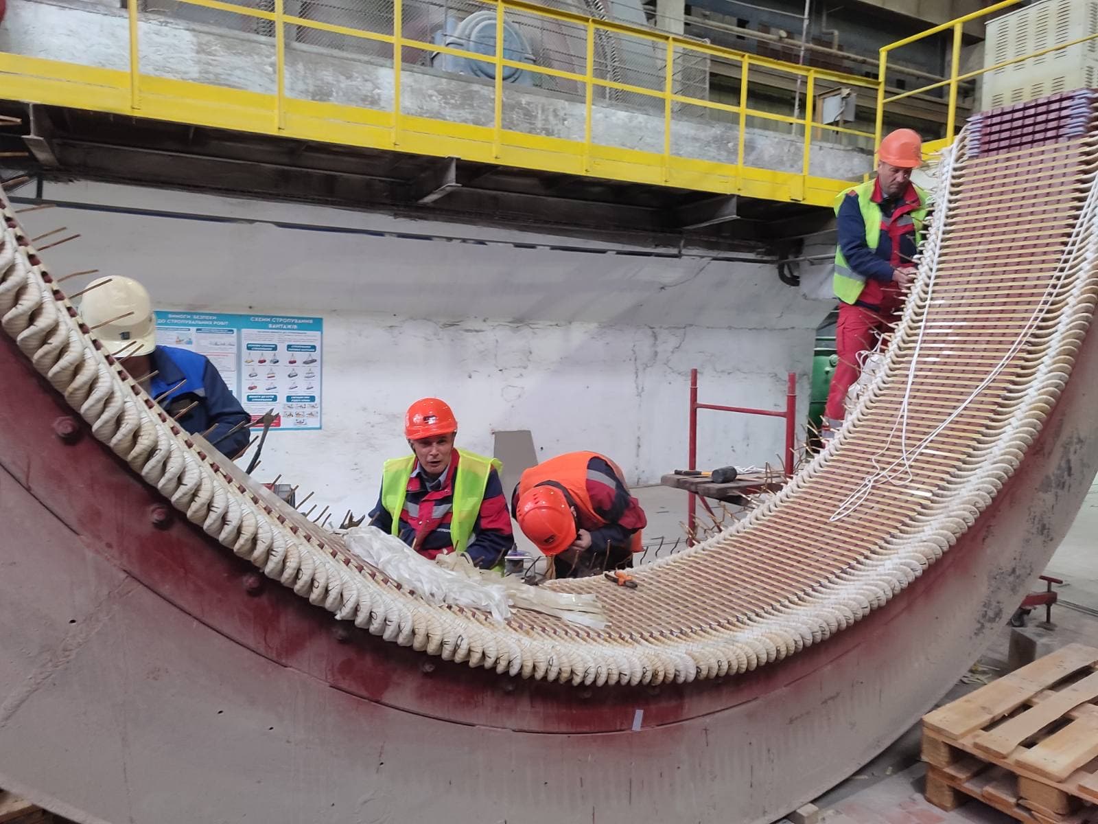
02

Severe damage to two phases

Possible causes:

  • loss of one phase;
  • a faulty contact;
  • a protection fault;
  • operation on a single-phasing supply.
03

Damage to one phase

Possible causes:

  • a local insulation defect;
  • a phase unbalance;
  • a weak connection;
  • an incorrect distribution of the parallel branches;
  • an error in a previous repair.
04

Damage in a single slot

Possible causes:

  • breakdown of the slot insulation;
  • a sharp edge on the core;
  • weak wedging;
  • movement of the conductors;
  • a foreign object;
  • local overheating of the core.
05

Damage to the end-turns

Possible causes:

  • loosening of the bandages;
  • electrodynamic forces during starting or a short circuit;
  • a phase-to-phase short circuit;
  • vibration;
  • insufficient clearance between phases;
  • contact with the frame or the rotor.
06

Damage near a connection

Possible causes:

  • poor soldering;
  • high contact resistance;
  • an insufficient cross-section;
  • mechanical loosening;
  • failure of the connection insulation.

Stage 3. Initial electrical measurements

If the condition of the winding allows, the following are carried out before it is removed:

  • measurement of the insulation resistance;
  • measurement of the phase resistance;
  • comparison of the inductance;
  • a symmetry check;
  • a check of the connection diagram;
  • a surge test;
  • a check for a short circuit between phases;
  • a check of the temperature sensors;
  • a check of the space heaters.

These results help to determine:

  • the nature of the fault;
  • the condition of the undamaged phases;
  • a possible error in the previous winding;
  • the presence of an open circuit in a parallel branch;
  • interturn asymmetry.

Stage 4. Recording the winding data

This is one of the most critical stages.

Before removing the old winding, the following must be recorded:

  • the number of stator slots;
  • the number of poles;
  • the number of phases;
  • the type of winding;
  • the number of layers;
  • the coil pitch;
  • the number of coils;
  • the number of coil groups;
  • the number of coils per group;
  • the number of turns per coil;
  • the number of parallel conductors;
  • the size of each conductor;
  • the number of parallel branches;
  • the connection diagram;
  • the winding direction;
  • the starts and ends of the phases;
  • the sequence of the coils;
  • the layout of the connections;
  • the position of the leads;
  • the length of the straight (in-slot) part;
  • the overhang of the end-turns;
  • the inner and outer dimensions of the coil;
  • the mass of copper;
  • the type of slot insulation;
  • the thickness of the insulation;
  • the type of wedges;
  • the type of phase-to-phase insulation;
  • the bandaging method;
  • the position of the sensors.

How the number of poles is determined

The number of poles can be determined from:

  • the rated speed on the nameplate;
  • the winding diagram;
  • the coil pitch;
  • the arrangement of the coil groups;
  • the number of slots per pole per phase;
  • the factory documentation.

The synchronous speed depends on the supply frequency and the number of pole pairs:

nₛ = 60 · f / p

where:

  • nₛ — the synchronous speed;
  • f — the supply frequency;
  • p — the number of pole pairs.

The actual speed of an asynchronous motor is lower than the synchronous speed because of slip.

An error in determining the number of poles completely changes the speed and the operating mode of the motor.

What the winding pitch is

The coil pitch is the number of slot divisions between the two sides of one coil.

It can be:

  • full pitch;
  • short pitch;
  • long pitch;
  • a special value for non-standard windings.

The pitch affects:

  • the winding factor;
  • the magnitude of the EMF;
  • the harmonics of the magnetic field;
  • the length of the end-turns;
  • the electromagnetic noise;
  • the starting characteristics.

The pitch must not be chosen merely for the convenience of laying the coils.

What the number of slots per pole per phase is

For a three-phase winding, this parameter is given by:

q = Z / (2p · m)

where:

  • q — the number of slots per pole per phase;
  • Z — the number of slots;
  • 2p — the number of poles;
  • m — the number of phases.

This value helps to determine the type and distribution of the winding.

For fractional-slot windings, q is not a whole number, so the diagram requires especially precise reproduction.

How turns are counted

The number of turns is determined:

  • by direct counting when dismantling a coil;
  • from the factory data sheet;
  • from the drawing;
  • from a similar, sound stator;
  • by calculation;
  • from the mass and length of the wire, as a supplementary method.

It is advisable to count the turns in several coils from different phases.

A final conclusion must not be drawn from a single, partially burnt coil.

Why the old winding may be incorrect

During a previous repair, someone may have:

  • changed the number of turns;
  • chosen the wrong wire;
  • changed the pitch;
  • reduced the number of parallel branches;
  • connected the groups incorrectly;
  • changed the overhang of the end-turns;
  • used weaker insulation;
  • determined the voltage incorrectly;
  • converted star to delta without a calculation.

The old winding therefore cannot automatically be treated as the factory reference.

Its data must be compared with:

  • the nameplate parameters;
  • the geometry of the core;
  • the rated current;
  • the manufacturer’s catalogues;
  • data from similar machines;
  • an electromagnetic calculation.

Checking the connection diagram

It is necessary to determine:

  • the start and end of each phase;
  • the number of parallel branches;
  • the sequence of the coil groups;
  • the internal links;
  • the star or delta connection;
  • the possibility of voltage switching;
  • the number of terminals;
  • the presence of a brought-out neutral point;
  • the connection of the sensors and space heaters.

The diagram must not just be described in words — it must also be drawn.

Star and delta

One and the same phase winding can have different line parameters depending on the connection scheme.

In a star connection:

  • the line voltage is greater than the phase voltage;
  • the line current equals the phase current.

In a delta connection:

  • the line voltage equals the phase voltage;
  • the line current is greater than the phase current.

An incorrect connection can cause:

  • excessive magnetic flux;
  • a high current;
  • overheating;
  • insufficient torque;
  • tripping of the protection;
  • rapid failure of the new winding.

Stage 5. Drawing up the winding data sheet

The data sheet must contain:

ParameterValue
Motor type
Power
Voltage
Frequency
Current
Speed
Number of slots
Number of poles
Number of phases
Type of winding
Number of layers
Coil pitch
Number of coils
Coils per group
Turns per coil
Conductors per turn
Wire size
Parallel branches
Connection diagram
Mass of copper
Slot insulation
Phase-to-phase insulation
Wedge type
Impregnation system
Sensor positions
Lead marking

The data sheet is accompanied by:

  • a slot development (unrolled) diagram;
  • a connection diagram;
  • a coil sketch;
  • photographs;
  • the position of the starts and ends;
  • the winding direction.

Stage 6. Removing the old winding

Before removal:

  1. 01The data recording is completed.
  2. 02The diagram is checked.
  3. 03A reference coil is set aside.
  4. 04The phases are marked.
  5. 05The position of the connections is recorded.
  6. 06The stator is weighed, or the mass of copper is estimated.
  7. 07The core is protected against mechanical damage.

How the old winding is removed

Depending on the design, the following are used:

  • mechanical cutting of the end-turns;
  • pulling out the coil sides;
  • softening the impregnating material;
  • controlled thermal removal;
  • combined methods;
  • special hydraulic or mechanical devices.

The main task is to remove the winding without damaging:

  • the teeth;
  • the slots;
  • the interlaminar insulation;
  • the ventilation ducts;
  • the pressure plates;
  • the frame.

Why uncontrolled burn-out is dangerous

Excessive heating of the core can cause:

  • destruction of the interlaminar insulation;
  • increased eddy currents;
  • local hot spots;
  • loosening of the core stack;
  • deformation of the core;
  • altered properties of the electrical steel;
  • damage to the frame;
  • reduced energy efficiency of the motor.

After such damage, the new winding may operate with an elevated current and overheat, even though its own insulation is sound.

The temperature regime during removal must be controlled in line with the materials and the technology of the specific facility.

What must not be done when removing the winding

It is not permitted to:

  • chisel out the conductors with heavy blows to the teeth;
  • use a chisel without protecting the core;
  • overheat the core stack with an open flame;
  • tear out coils together with pieces of the slots;
  • damage the ventilation spacers;
  • mix up fragments before the turn count is complete;
  • remove the reference coil without measuring it;
  • leave copper particles between the laminations;
  • grind the slots with coarse abrasive without necessity.

Stage 7. Cleaning the slots

After removal, the following are removed:

  • residues of the slot insulation;
  • copper particles;
  • varnish;
  • carbon deposits;
  • dust;
  • burrs;
  • sharp edges;
  • contamination of the ventilation ducts.

Cleaning is carried out so as not to create:

  • shorted laminations;
  • enlarged slots;
  • damage to the teeth;
  • new sharp edges;
  • irregularities that would damage the new insulation.

After cleaning, the slots are inspected under adequate lighting.

Stage 8. Inspecting the stator core

Before fitting the new winding, the serviceability of the core must be confirmed.

The following are checked:

  • traces of rotor contact;
  • melting or scorching;
  • blue or dark areas;
  • shorted laminations;
  • damage to the teeth;
  • loosening of the core stack;
  • corrosion;
  • foreign particles;
  • the condition of the ventilation ducts;
  • the condition of the pressure plates;
  • the condition of the tie rods;
  • the geometry of the bore.

Ring flux (loop) test of the core

A magnetic flux is set up around the core and its heating is monitored.

The method helps to reveal:

  • elevated losses;
  • local interlaminar short circuits;
  • hot spots;
  • damage from burn-out;
  • traces of accidental rotor contact.

The following are monitored:

  • the flux density;
  • the test duration;
  • the overall temperature;
  • the local temperature difference;
  • the stability of the regime.

Simply heating the core without controlling the magnetic regime does not give a comparable result.

Low-flux core test methods

Systems that detect currents between damaged laminations at a relatively low magnetic flux may be used (for example, EL CID-type methods).

Advantages:

  • less overall heating;
  • localisation of the defect;
  • digital recording;
  • convenience for large stators.

Limitations:

  • special equipment is required;
  • the result depends on the setup and the operator’s skill;
  • not all defects are equally well detected by a single method.

For critical machines, it is advisable to combine different types of testing.

How local core damage is repaired

Depending on the defect, the following may be used:

  • removing shorted metal burrs;
  • separating shorted laminations;
  • restoring the insulation;
  • fitting insulating material;
  • local machining;
  • replacing a damaged segment;
  • re-stacking the core;
  • restoring the clamping pressure of the core stack.

After repair, the core must be re-tested.

Checking the stator geometry

The following are checked:

  • the bore diameter;
  • ovality;
  • taper;
  • concentricity;
  • deformation of the frame;
  • the condition of the centring fits;
  • the position of the core in the frame;
  • the flatness of the feet or the flange.

Rewinding does not correct mechanical deformation of the stator. If the geometry is out of tolerance, an uneven air gap can result after assembly.

Stage 9. Selecting the insulation system

The insulation system is not a single material but a compatible set:

  • the wire enamel insulation;
  • the slot insulation;
  • the interlayer insulation;
  • the phase-to-phase insulation;
  • the insulation of the connections;
  • the wedges;
  • the bandaging materials;
  • the impregnating varnish or resin;
  • the sealing materials;
  • the protective coating.

The materials must be mutually compatible in terms of:

  • temperature;
  • chemical composition;
  • adhesion;
  • the drying process;
  • mechanical strength;
  • moisture resistance;
  • the operating conditions.

Thermal class of the insulation

The insulation class characterises the permissible temperature resistance of the material system.

However, the insulation class does not mean that the motor should constantly operate at the maximum permissible temperature of that class.

The actual service life depends on:

  • the winding temperature;
  • thermal cycling;
  • vibration;
  • humidity;
  • contamination;
  • overvoltages;
  • the quality of the impregnation;
  • the mechanical fastening.

Using a higher-class material does not compensate for:

  • an incorrect number of turns;
  • overload;
  • poor cooling;
  • poor coil laying;
  • a damaged core.

Thickness of the slot insulation

The thickness is determined by:

  • the rated voltage;
  • the winding design;
  • the shape of the slot;
  • the type of conductor;
  • the laying technology;
  • the electrical tests;
  • the manufacturer’s requirements;
  • the mechanical loads.

Insulation that is too thin may fail to provide adequate electrical and mechanical strength.

Insulation that is too thick:

  • reduces the space available for copper;
  • increases the fill factor;
  • makes laying more difficult;
  • impairs heat transfer;
  • may force excessive compaction of the conductors.

Features of high-voltage stator insulation

For high-voltage machines, the following are critical:

  • the main insulation of the coils;
  • the distribution of the electric field;
  • protection against corona;
  • semi-conductive coatings;
  • stress-grading coatings on the end-turns;
  • the absence of air voids;
  • partial discharge monitoring;
  • precise insulation thickness;
  • vacuum-pressure impregnation or another special technology.

Such coils are usually manufactured as form-wound sections with multi-layer insulation.

Low-voltage motor repair methods cannot automatically be carried over to a high-voltage machine.

Insulation for operation with a frequency converter

When supplied from a converter, the winding is subjected to:

  • pulse voltage;
  • steep voltage rise times;
  • an uneven voltage distribution across the first turns;
  • high-frequency components;
  • repetitive overvoltages;
  • additional heating.

The following may be required:

  • wire with enhanced surge resistance;
  • reinforced interturn insulation;
  • reliable phase-to-phase insulation;
  • special treatment of the first turns;
  • output filters;
  • cable-length limits;
  • adjustment of the converter settings.

Stage 10. Manufacturing the coils

Coils are manufactured on formers or on special winding equipment.

Before winding, the following are determined:

  • the shape;
  • the dimensions;
  • the number of turns;
  • the direction;
  • the number of parallel conductors;
  • the tension;
  • the position of the start and end;
  • the permissible bend radius;
  • the process allowance.

The coil former

The former must ensure:

  • the required length of the straight part;
  • the correct pitch;
  • equal overhang of the end-turns;
  • adequate clearance to the rotor and the end shields;
  • the ability to be laid into the slots;
  • room for the insulation;
  • symmetry of all the coils.

A coil that is too large:

  • increases the length of copper;
  • increases the resistance;
  • impairs cooling;
  • may touch the frame or an end shield;
  • makes bandaging more difficult.

A coil that is too small:

  • cannot be fitted without excessive deformation;
  • creates mechanical stress;
  • can damage the insulation;
  • changes the position of the end-turns.

Controlling the wire tension

The tension must be:

  • sufficient for uniform laying;
  • consistent;
  • without deforming the conductor;
  • without damaging the enamel;
  • without excessive stretching.

Uneven tension can lead to:

  • coils of differing geometry;
  • crossed conductors;
  • voids;
  • weak fastening;
  • damaged insulation.

Winding with several parallel wires

During winding, the following must be ensured:

  • equal length of the conductors;
  • the correct relative arrangement of the conductors;
  • the absence of crossovers;
  • uniform tension;
  • correct connection of the ends;
  • equal current distribution.

If one of the parallel conductors has a weak connection or an open circuit, the overall phase resistance may change only slightly, but the local overheating will be significant.

Form-wound coils

For large and high-voltage machines, coils may be manufactured as rigid, form-wound sections.

The process includes:

  • winding the conductors;
  • insulating the turns;
  • shaping the sides;
  • pressing;
  • applying the main insulation;
  • heat treatment;
  • applying the protective coatings;
  • electrical testing of each section;
  • geometry checks.

Such coils must precisely match the slots and the end-winding zone of the specific stator.

Stage 11. Interim testing of the coils

Before laying, the following are checked:

  • the number of turns;
  • continuity;
  • the resistance;
  • the winding direction;
  • the geometry;
  • the dimensions;
  • the quality of the insulation;
  • the absence of shorts;
  • the marking of the start and end.

If necessary, the following are performed:

  • a comparative surge test;
  • an insulation test;
  • measurement of the dielectric loss angle;
  • partial discharge monitoring;
  • capacitance measurement.

A coil defect is far easier to correct before the coil is laid into the stator.

Stage 12. Fitting the slot insulation

The slot insulation must:

  • fully cover the metal of the slot;
  • have no tears;
  • project by the required length;
  • protect the conductors where they leave the slot;
  • have no sharp folds;
  • withstand the laying process;
  • be compatible with the impregnation.

Particular attention is paid to:

  • the corners of the slot;
  • the exit from the core;
  • damaged teeth;
  • the joints;
  • the areas under the wedges.

Sleeves and collars at the slot exits

At the slot exit, the winding is subjected to:

  • bending;
  • vibration;
  • thermal expansion;
  • electrodynamic forces;
  • contact with the edge of the core.

For protection, the following may be used:

  • additional strips;
  • collars;
  • sleeves;
  • formed insulating elements;
  • tape reinforcement.

With insufficient protection, this area often becomes the site of a breakdown.

Stage 13. Laying the coils into the slots

Laying is carried out in the sequence defined by the winding diagram.

The following must be checked:

  • the slot number;
  • the phase;
  • the direction;
  • the top and bottom layer;
  • the position of the coil sides;
  • the pitch;
  • the crossing of the end-turns;
  • the start and end;
  • the condition of the insulation after laying.

How a soft, random-wound winding is laid

For low-voltage machines, soft coils are often used, formed and laid either by hand or with mechanised equipment.

A typical sequence:

  1. 01Fitting the slot insulation.
  2. 02Laying the bottom coil sides.
  3. 03Fitting the interlayer insulation.
  4. 04Laying the top sides.
  5. 05Fitting the slot closure elements.
  6. 06Wedging.
  7. 07Forming the end-turns.
  8. 08Connecting the groups.
  9. 09Bandaging.

The use of sharp metal tools without insulating protection must be avoided.

Laying rigid sections

Form-wound sections are fitted with checks of:

  • the geometry;
  • the clearances;
  • the condition of the main insulation;
  • the position in the slot;
  • the radial packing;
  • the compaction;
  • the exit of the end-turns;
  • the semi-conductive coatings;
  • the stress-grading zone.

Damage to the surface protective layer can lead to partial discharges even without a direct breakdown.

What must not be done during laying

It is not permitted to:

  • hammer the coils in with a metal mallet;
  • pull on the leads;
  • sharply bend the wire;
  • damage the enamel;
  • over-compress a coil;
  • leave torn slot insulation;
  • allow bare metal to be exposed;
  • lay contaminated coils;
  • change slots without adjusting the whole diagram;
  • over-compact the slot;
  • leave loose conductors.

Slot fill factor

The slot must accommodate:

  • the conductors;
  • the slot insulation;
  • the interlayer insulation;
  • process clearances;
  • the closure materials;
  • the wedge.

An excessive fill factor leads to:

  • difficult laying;
  • damage to the enamel;
  • damage to the slot insulation;
  • poor penetration of the varnish;
  • internal voids;
  • mechanical pressure on the conductors;
  • reduced repairability.

Too low a fill factor allows the conductors to move under electromagnetic forces.

Stage 14. Interlayer and phase-to-phase insulation

In a two-layer winding, insulation is fitted between the top and bottom layers that:

  • separates the coil sides;
  • protects against damage during laying;
  • provides the required dielectric strength;
  • prevents mechanical chafing.

Between phases in the end-winding region there must be a reliable insulating clearance or special separators.

Particularly important locations are:

  • coil crossovers;
  • the phase connections;
  • the leads to the terminal box;
  • areas near the bandages;
  • zones of closest mechanical proximity.

Stage 15. Wedging the winding

Slot wedges hold the conductors inside the slots.

They must provide:

  • mechanical retention;
  • uniform pressure;
  • resistance to vibration;
  • compatibility with the impregnation;
  • heat resistance;
  • no damage to the insulation.

The following are checked:

  • the material;
  • the dimensions;
  • the fit tightness;
  • the absence of cracks;
  • the position;
  • protrusion;
  • the condition of the slot closures.

Why loose wedges are dangerous

Loosening of the wedges can lead to:

  • movement of the coil sides;
  • abrasion of the insulation;
  • vibration of the winding;
  • electromagnetic noise;
  • partial discharges;
  • an interturn short circuit;
  • destruction of the winding on starting.

Overly tight wedges are also dangerous, since they can damage the insulation or deform a tooth.

Stage 16. Forming the end-turns

The end-turns must:

  • have consistent geometry;
  • not touch the frame;
  • not touch the rotor;
  • not obstruct ventilation;
  • have adequate phase-to-phase clearance;
  • withstand electrodynamic forces;
  • not put excessive tension on the in-slot sides;
  • not interfere with fitting the end shields.

The geometry is checked with templates and measurements.

Why end-turns fail

The main causes:

  • insufficient bandaging;
  • excessive overhang;
  • poor impregnation;
  • short circuits;
  • frequent heavy starts;
  • vibration;
  • mechanical resonance;
  • poor laying;
  • contact with stationary parts;
  • loosening of the support rings.

The end-turns must therefore be not only electrically insulated but also mechanically engineered.

Stage 17. Connecting the coil groups

Connections are made in accordance with the diagram.

Methods:

  • soldering;
  • welding;
  • crimping;
  • bolted joints;
  • special contact elements.

Every connection must have:

  • the required electrical cross-section;
  • low contact resistance;
  • mechanical strength;
  • good-quality insulation;
  • resistance to heat;
  • resistance to vibration.

Soldering the connections

During soldering, the following are checked:

  • surface cleaning;
  • the correct solder;
  • the appropriate flux;
  • the temperature;
  • complete wetting;
  • the absence of a cold joint;
  • removal of residual active flux;
  • mechanical reinforcement;
  • insulation.

A connection subject to significant mechanical loads must not rely on the solder alone to hold it together.

Welding the conductors

Welding can provide a reliable contact, but it requires control of:

  • the process parameters;
  • the heat input;
  • the cross-section;
  • the quality of the joint;
  • the absence of burn-through;
  • the absence of sharp burrs;
  • mechanical strength.

Excessive heating can damage the insulation of adjacent areas.

Insulating the connections

Once the contact is made, it is insulated with a system that matches:

  • the voltage;
  • the thermal class;
  • the geometry;
  • the impregnation conditions;
  • the mechanical loads.

The following must not be left:

  • sharp edges;
  • protruding ends;
  • air voids;
  • loosely secured tapes;
  • flux contamination;
  • insufficient overlap length.

Stage 18. Marking the leads

The leads must be:

  • correctly identified;
  • mechanically secured;
  • protected against chafing;
  • of sufficient length;
  • compatible with the terminals;
  • correctly insulated;
  • free of tension.

The marking must match the diagram and the documentation.

After assembly, the following are checked for consistency:

  • the starts and ends of the phases;
  • the phase sequence;
  • the links;
  • the connection voltage;
  • the direction of rotation.

Stage 19. Fitting the temperature sensors

If the design includes temperature sensors, they are fitted:

  • in the specified phases;
  • in the most thermally loaded zones;
  • with good thermal contact;
  • without damaging the main insulation;
  • with protected leads.

Before and after impregnation, the following are checked:

  • the resistance;
  • the insulation;
  • the marking;
  • the wiring diagram.

A sensor mounted too far from the conductors may show the temperature with a delay, or read it too low.

Stage 20. Bandaging the end-turns

The bandages and cords must:

  • hold the coils in place;
  • distribute the load;
  • not damage the insulation;
  • be heat-resistant;
  • be impregnated together with the winding;
  • not loosen after drying.

Bandaging is carried out at the specified locations with controlled tension.

Excessive tension can deform the coils. Insufficient tension will not provide adequate mechanical strength.

Stage 21. Checks before impregnation

Before impregnation, the most thorough possible checks are carried out, because correcting mistakes after curing will be difficult.

The following are checked:

  • the diagram;
  • the number of groups;
  • the starts and ends of the phases;
  • the phase direction;
  • the resistance;
  • the symmetry;
  • the insulation resistance;
  • the absence of a short to the frame;
  • the interturn insulation;
  • the phase-to-phase insulation;
  • the position of the coils;
  • the wedges;
  • the bandages;
  • the connections;
  • the marking;
  • the sensors;
  • the geometry of the end-turns;
  • the clearances.

Checking the polarity of the coil groups

An incorrectly connected group can produce a magnetic field opposing the other groups.

Consequences:

  • a high current;
  • loud noise;
  • the absence of normal torque;
  • local overheating;
  • electromagnetic asymmetry.

Polarity is checked using special methods before impregnation and before applying full voltage.

Measuring the resistance

The phase resistance is measured with a precision instrument.

A four-wire (Kelvin) method is advisable, especially for low-resistance windings.

The following must be recorded:

  • the winding temperature;
  • the connection diagram;
  • the resistance of each phase;
  • the resistance between leads;
  • the stability of the readings.

Asymmetry can indicate:

  • a different number of turns;
  • a poor connection;
  • an open circuit in a parallel conductor;
  • an incorrect diagram;
  • a different cross-section.

Surge testing

The surge test compares the response of the windings to a short high-voltage pulse.

It can help to reveal:

  • interturn defects;
  • a difference in the number of turns;
  • asymmetry between coils;
  • weak points in the interturn insulation.

Limitations:

  • correct connection is required;
  • the results depend on the geometry and the capacitance;
  • comparing different phases is not possible for every diagram without additional analysis;
  • excessive test voltage can damage the insulation;
  • the test does not replace an insulation test to the frame.

Stage 22. Pre-drying

Before impregnation, the winding is often dried to remove:

  • moisture;
  • solvents;
  • condensate;
  • residues of cleaning agents.

Moisture inside the winding can:

  • impair the penetration of the varnish;
  • create pores;
  • reduce adhesion;
  • reduce the dielectric strength;
  • cause curing defects.

The temperature and the insulation resistance are monitored.

Stage 23. Impregnating the winding

Impregnation simultaneously performs an electrical, mechanical, thermal and protective function.

It must:

  • fill the voids;
  • bond the conductors together;
  • secure the insulation;
  • protect against moisture;
  • improve heat transfer;
  • reduce vibration;
  • increase resistance to contamination.

The main impregnation methods

Dip impregnation

The stator is dipped into the impregnating material.

Advantages:

  • relative simplicity;
  • treatment of the whole winding;
  • suitability for many low-voltage machines.

Limitations:

  • air voids are possible;
  • penetration depends on the viscosity and the time;
  • good-quality pre-drying is required;
  • it is difficult to fully impregnate a very densely wound coil.

Trickle impregnation

The material is metered onto the winding, sometimes while it is rotating and heated.

Advantages:

  • controlled consumption;
  • the possibility of automation;
  • good filling of certain winding types.

Limitations:

  • a precise regime is required;
  • it is not suitable for every design;
  • there is a risk of uneven distribution.

Vacuum impregnation

Air is removed from the winding, after which varnish or resin is introduced.

Advantages:

  • better air removal;
  • deeper penetration;
  • fewer voids.

Limitations:

  • special equipment is required;
  • the result depends on the tightness of the seal and the process regime;
  • the viscosity of the material is of great importance.

Vacuum-pressure impregnation

After evacuation, the material is fed in under pressure.

Advantages:

  • deep penetration;
  • high mechanical strength;
  • good electrical resistance;
  • effectiveness for large and high-voltage machines.

Limitations:

  • complex, costly equipment;
  • precise material compatibility is required;
  • repair after full curing becomes more difficult;
  • not every design is rated for the same regime.

How the impregnating material is selected

The following are taken into account:

  • the thermal class;
  • the viscosity;
  • the penetrating ability;
  • the curing regime;
  • the adhesion;
  • the thermal conductivity;
  • the elasticity;
  • the chemical resistance;
  • the moisture resistance;
  • compatibility with the wire and the insulation;
  • the operating conditions;
  • the possibility of future repair.

A system that is too rigid can crack under thermal cycling. One that is too soft will not hold the winding adequately.

Checking the impregnating material

The following are checked:

  • the shelf life;
  • the storage conditions;
  • the viscosity;
  • the temperature;
  • contamination;
  • the solvent content;
  • the homogeneity;
  • the batch conformity;
  • the curing schedule.

Using expired or improperly stored material can produce a coating that looks normal on the outside but has insufficient curing inside the winding.

Stage 24. Drying and curing

After impregnation, the winding is held according to the regime specified by the material manufacturer and the process.

The following are monitored:

  • the heating rate;
  • the oven temperature;
  • the actual stator temperature;
  • the winding temperature;
  • the holding time;
  • the ventilation;
  • the removal of vapours;
  • the cooling rate.

The air temperature in the oven and the temperature of the massive stator can differ significantly.

Why drying "by appearance" is not acceptable

The surface can become dry before:

  • the material inside the slots has cured;
  • the solvent has been removed from the inner layers;
  • the core has heated through;
  • the insulation has stabilised.

Insufficient curing leads to:

  • a tacky surface;
  • movement of the conductors;
  • weak mechanical retention;
  • odour and off-gassing;
  • reduced dielectric strength;
  • contamination of the machine.

The danger of excessive temperature

Overheating during drying can:

  • damage the wire enamel;
  • accelerate ageing of the materials;
  • cause cracking;
  • deform plastic components;
  • damage the sensors;
  • cause excessive resin run-off;
  • alter the mechanical properties of the bandages.

The regime must be controlled according to the process specification, not simply the operator’s experience.

Multiple impregnation

For some windings, several cycles are applied:

  1. 01Drying.
  2. 02First impregnation.
  3. 03Curing.
  4. 04Inspection.
  5. 05Re-impregnation.
  6. 06Final curing.

The purpose:

  • better filling;
  • forming a protective layer;
  • increasing mechanical strength;
  • protecting the end-turns.

However, more varnish does not always improve the result. An excess can block the ventilation ducts and impede cooling.

Stage 25. Cleaning after impregnation

After curing, varnish is removed from surfaces where it must not remain:

  • the centring fits;
  • threads;
  • mating surfaces;
  • earthing contacts;
  • terminals;
  • sensor mounting locations;
  • frame joints;
  • ventilation ducts;
  • fastening holes.

The winding insulation must not be damaged during mechanical cleaning.

Stage 26. Final electrical tests

After drying and cooling, the following are carried out:

  • measurement of the insulation resistance;
  • determination of the absorption coefficient;
  • determination of the polarization index where required;
  • measurement of the phase resistance;
  • a symmetry check;
  • a surge test;
  • a phase-to-phase insulation test;
  • a test to the frame;
  • a check of the diagram;
  • a polarity check;
  • a check of the sensors;
  • a check of the space heaters;
  • partial discharge monitoring for the relevant machines.

High-voltage testing

The purpose is to verify the dielectric strength of the insulation to the frame and between electrically separate circuits.

Before the test:

  • the insulation resistance is checked;
  • sensitive components are disconnected;
  • the necessary leads are bonded together;
  • parts are earthed in accordance with the diagram;
  • a current limit is set;
  • the area is cordoned off;
  • the emergency trip is checked.

After the test, the winding is discharged and earthed.

The test voltage and duration must not be chosen arbitrarily. They depend on the rated voltage, the type of repair, the age of the insulation, the design and the applicable requirements.

Why the high-voltage test must not be repeated needlessly

Every test places an electrical stress on the insulation.

Repeating it without justification can:

  • accelerate ageing;
  • damage a weak but still serviceable spot;
  • create a risk of breakdown;
  • provide no new diagnostic information.

A repeat test must be justified by the process, or by the need to confirm the repair.

Checking phase symmetry

The following are compared:

  • the resistance;
  • the inductance;
  • the surge-test response;
  • the phase currents after assembly;
  • the magnetic response.

A difference may be linked to:

  • a different number of turns;
  • a connection error;
  • an open circuit in a parallel conductor;
  • a weak contact;
  • an incorrect pitch;
  • inconsistent geometry;
  • a core defect.

Stage 27. Magnetic checks of the stator

Before the rotor is fitted, or during a check with a reduced supply voltage, the following may be verified:

  • the correct alternation of the poles;
  • the symmetry of the magnetic field;
  • the correct connection of the coil groups;
  • the phase currents;
  • local heating;
  • electromagnetic noise.

Such checks must be carried out using a safe circuit with current limiting.

Stage 28. Assembling the motor

Once testing is complete, the stator is incorporated into the overall assembly process.

Before inserting the rotor, the following are checked:

  • the internal surface of the stator;
  • the absence of foreign objects;
  • the fastening of the wedges;
  • the geometry of the end-turns;
  • the clearances;
  • the condition of the leads;
  • the condition of the sensors;
  • the cleanliness of the ventilation ducts.

When fitting the rotor, contact with the winding must not be allowed to occur.

Stage 29. No-load testing

After assembly, the following are checked:

  • the direction of rotation;
  • the starting;
  • the current in each phase;
  • the symmetry of the currents;
  • the no-load current;
  • the noise;
  • the vibration;
  • the temperature;
  • the operation of the fan;
  • the operation of the bearings;
  • the absence of any odour;
  • the condition of the terminal connections.

The test is started with a controlled regime and working protection.

Why the no-load current may be high after rewinding

Possible causes:

  • a reduced number of turns;
  • an incorrect connection;
  • an incorrect pitch;
  • an incorrect number of parallel branches;
  • a damaged core;
  • an uneven air gap;
  • a rotor defect;
  • excessive voltage;
  • mechanical friction;
  • an incorrect supply frequency.

A high current should not be considered normal just because the motor turns.

Why the phase currents may differ

The causes can be internal or external.

Internal:

  • different phase resistance;
  • a diagram error;
  • an incorrect group;
  • an open circuit in a parallel conductor;
  • an uneven air gap;
  • a rotor defect;
  • damage to the core.

External:

  • a voltage unbalance;
  • poor contacts;
  • different cable resistance;
  • an unstable supply.

The currents and the phase voltages must be measured at the same time.

Why the motor hums after rewinding

Possible causes:

  • an incorrectly connected coil group;
  • phase asymmetry;
  • an incorrect pitch;
  • weak wedging;
  • movement of the conductors;
  • a core defect;
  • an uneven air gap;
  • a rotor defect;
  • resonance of the frame;
  • incorrect voltage.

Loud electromagnetic noise can be a sign of a serious error even when the insulation resistance is acceptable.

Why the new winding overheats

The main causes:

  • an incorrect number of turns;
  • insufficient copper cross-section;
  • a poor connection;
  • a damaged core;
  • poor cooling;
  • blocked ventilation ducts;
  • an excessive layer of varnish;
  • overload;
  • frequent starts;
  • low speed under frequency-converter control;
  • a rotor defect;
  • a voltage unbalance;
  • incorrect protection.

The thermal class of the materials does not eliminate the cause of excessive heat generation.

Testing under load

For critical machines, it is advisable to check:

  • the phase currents;
  • the active power;
  • the power factor;
  • the speed;
  • the slip;
  • the torque;
  • the efficiency;
  • the heating;
  • the vibration;
  • the behaviour during starting.

Not every winding error is fully revealed at no load.

How energy efficiency changes after rewinding

Energy efficiency can deteriorate because of:

  • damage to the core;
  • an increase in the length of the end-turns;
  • a reduction in the copper cross-section;
  • an incorrect number of turns;
  • a worse fill factor;
  • increased ventilation losses;
  • an incorrect connection;
  • a change in the magnetic flux.

A quality rewinding job should preserve the original electromagnetic characteristics as closely as possible.

Can the motor voltage be changed during rewinding

Technically, this is possible in certain cases, but it requires an electromagnetic calculation.

The following must be checked:

  • the number of turns;
  • the wire cross-section;
  • the current;
  • the connection diagram;
  • the insulation;
  • the slot fill;
  • the starting characteristics;
  • the magnetic flux;
  • the thermal regime;
  • the terminal box;
  • the protection.

A simple star-to-delta change does not always allow the motor to be converted to any other voltage.

Can the speed be changed by rewinding

Changing the number of poles changes the synchronous speed, but this is a rebuild, not an ordinary rewinding job.

The following must be assessed:

  • the suitability of the slot system;
  • the rotor geometry;
  • the starting torque;
  • the power;
  • the cooling;
  • the mechanical speed;
  • the fan;
  • the bearings;
  • the connected machinery.

Not every motor can be safely converted to a different speed.

Can the motor power be increased

The power is limited not only by the winding but also by:

  • the dimensions of the core;
  • the magnetic flux density;
  • the heat dissipation;
  • the air gap;
  • the rotor;
  • the shaft;
  • the bearings;
  • the fan;
  • the frame;
  • the duty type.

Increasing the wire cross-section by itself does not turn the motor into a higher-power machine.

Features of rewinding explosion-proof motors

For explosion-proof machines, the following are critical:

  • preserving the certified design;
  • the surface temperature;
  • the insulation system;
  • the clearances and creepage distances;
  • the terminal devices;
  • the seals;
  • the gaps of the flameproof enclosure;
  • material compliance;
  • documenting the repair.

An arbitrary change to the winding data or the design can compromise the explosion protection.

Features of rewinding high-voltage motors

The following are needed:

  • precise coil drawings;
  • form-wound sections;
  • multi-layer main insulation;
  • thickness control;
  • corona protection;
  • vacuum-pressure impregnation or another specified system;
  • partial discharge monitoring;
  • testing of every coil;
  • control of the electric field;
  • special laying and wedging methods.

The quality of such a winding cannot be assessed with a megohmmeter and a test to the frame alone.

Features of dual-speed motors

Dual-speed windings may have:

  • pole-changing switching;
  • two independent windings;
  • a complex connection diagram;
  • several sets of leads;
  • different rated currents.

Before removal, it is especially important to:

  • record all the links;
  • check the diagram;
  • mark every lead;
  • draw up a complete slot development;
  • check the directions of the magnetic fields at both speeds.

Features of multi-section and special-purpose windings

Certain machines may have:

  • several parallel circuits;
  • a sectioned winding;
  • leads for starting;
  • built-in current transformers;
  • special sensors;
  • compensating windings;
  • braking windings;
  • a non-standard number of phases.

Such windings cannot be reproduced from a standard table alone.

Diagnostic table after rewinding

ObservationPossible causeRecommended check
High current in all phasesToo few turns, a damaged core, high voltageCheck the turns, the diagram, the voltage and the core
High current in one phaseA connection error or a weak contactMeasure the resistance and check the groups
Loud humIncorrect polarity, air gap, rotorMagnetic check, currents, air gap
Motor fails to reach speedIncorrect diagram, rotor, insufficient torqueCheck the connections and the rotor
Overheating at a connectionHigh contact resistanceThermal and contact inspection
Local overheating of the statorCore or a local winding defectThermal imaging, surge test
Low insulation resistanceMoisture, contamination, an impregnation defectDrying and repeat measurements
Breakdown during testingDamaged main insulationLocalisation and repair
Unequal phase resistanceDifferent turns, an open circuit in a parallel conductorCheck the diagram and the connections
Vibration at no loadElectromagnetic asymmetry or a mechanical defectSpectrum analysis, currents, air gap, rotor
Smell of varnish after prolonged runningInsufficient curing or overheatingTemperature, drying regime
Loosening of the wedgesIncorrect size or shrinkageRe-wedging
Sparking in the terminal boxA weak connection or damaged insulationInspection of the terminals and leads
Overheating when running from a frequency converterPulse loading or poor coolingCheck the insulation, filters and ventilation

What should not be done

01

Do not remove the old winding before recording the data

After removal, some of the parameters can no longer be reliably recovered.

02

Do not copy the old winding without checking it

It may have been rewound incorrectly before.

03

Do not determine the wire size using calipers alone

The enamel, the number of parallel conductors and the total copper cross-section must all be taken into account.

04

Do not reduce the number of turns for the convenience of laying

This raises the magnetic flux and the current.

05

Do not arbitrarily increase the wire cross-section

The slot fill, the cooling and the geometry must be checked.

06

Do not burn out the winding with an open flame

This can destroy the core.

07

Do not lay the new winding without checking the core

A local hot spot will damage the new insulation.

08

Do not use incompatible insulating materials

The system may delaminate or fail to cure.

09

Do not work on the winding with a sharp metal tool

Even invisible damage to the enamel can become the site of a future short circuit.

10

Do not leave loose wedges

Movement of the conductors destroys the insulation.

11

Do not connect the groups without checking the polarity

The motor can draw a dangerously high current.

12

Do not impregnate an unchecked winding

After curing, correcting mistakes becomes far more difficult.

13

Do not dry without controlling the temperature

The oven temperature does not indicate the actual temperature of the winding.

14

Do not block the ventilation ducts with varnish

This impairs cooling.

15

Do not assess the result with a megohmmeter alone

A full set of electrical and functional tests is required.

16

Do not release the motor without a no-load test

The correctness of the winding must be confirmed in the assembled machine.

Common mistakes during rewinding

  1. 01No data sheet for the old winding.
  2. 02The exact number of turns was not counted.
  3. 03The number of parallel branches was not determined.
  4. 04The wire was measured incorrectly.
  5. 05The thickness of the new insulation was not taken into account.
  6. 06The wrong connection diagram was chosen.
  7. 07The starts and ends of the phases were mixed up.
  8. 08Incorrect polarity of a coil group.
  9. 09The pitch was changed without a calculation.
  10. 10End-turns that are too large.
  11. 11Excessively tight slot fill.
  12. 12Enamel damaged during laying.
  13. 13Torn slot insulation.
  14. 14Missing phase-to-phase insulation at critical points.
  15. 15Weak wedging.
  16. 16Insufficient bandaging.
  17. 17A cold soldered joint.
  18. 18Residue of active flux.
  19. 19Insufficient insulation of the connections.
  20. 20Expired varnish was used.
  21. 21The winding was impregnated while still damp.
  22. 22Incorrect curing regime.
  23. 23The temperature sensors were not checked.
  24. 24No surge test was carried out.
  25. 25The phase resistance was not measured.
  26. 26The core was not checked.
  27. 27The ventilation ducts were not cleaned.
  28. 28The rotor was not checked after assembly.
  29. 29No no-load test was carried out.
  30. 30The root cause of the original failure was not established.

Case studies

01

After rewinding, the motor draws a much higher current

It is necessary to check:

  • the number of turns;
  • the connection diagram;
  • the polarity of the groups;
  • the frequency and the voltage;
  • the core;
  • the air gap;
  • the rotor;
  • mechanical friction.

The elevated current should not be explained away simply as "the winding is new and has not yet bedded in."

02

The phase resistance is equal, but the motor hums

Equal resistance does not guarantee:

  • an equal number of turns;
  • correct polarity;
  • a correct spatial layout;
  • the absence of an interturn defect;
  • a sound core;
  • a uniform air gap.

Magnetic, surge and functional checks are required.

03

After impregnation, the insulation resistance has worsened

Possible causes:

  • moisture in the winding;
  • insufficient drying;
  • contaminated material;
  • residual solvent;
  • damage during handling;
  • an incorrect curing regime;
  • conductive dirt on the surface.

The cause must be established before the high-voltage test.

04

The new winding has a strong smell during the no-load test

Possible causes:

  • insufficient curing;
  • residual solvent;
  • overheating;
  • varnish on hot surfaces;
  • local contact;
  • excessive current.

A smell should not automatically be considered normal for a new winding.

05

A few months later, the winding burned out again

Possible causes:

  • an unresolved cause of overload;
  • loss of a phase;
  • incorrect protection;
  • a rotor defect;
  • insufficient cooling;
  • weak wedging;
  • a damaged core;
  • incorrect winding data;
  • operation from a frequency converter without the necessary measures.

The pattern of both failures and the operating conditions must be analysed.

06

After rewinding, the motor fails to develop torque

The following are checked:

  • the number of poles;
  • the diagram;
  • the connection of the groups;
  • the number of turns;
  • the voltage;
  • the rotor;
  • the phasing;
  • the parallel branches;
  • the starting equipment.
07

The end-turns vibrate during operation

Causes:

  • insufficient bandaging;
  • poor impregnation;
  • excessive overhang;
  • incorrect supports;
  • high starting currents;
  • electromagnetic asymmetry;
  • resonance.

Applying extra varnish on the surface does not always fix the underlying mechanical problem.

The complete stator rewinding algorithm

STEP 01

Receive and identify the motor

Record all the nameplate data and the operating conditions.

STEP 02

Analyse the failure

Determine the probable cause of the damage.

STEP 03

Carry out the initial measurements

Insulation resistance, phase resistance, surge testing and other diagnostics.

STEP 04

Record the damage pattern

Photographs and a description of each phase and zone.

STEP 05

Record the winding data

Turns, pitch, wire, diagram, branches, geometry.

STEP 06

Draw up the data sheet and the diagram

Before removing the old winding.

STEP 07

Remove the old winding

Without overheating or damaging the core.

STEP 08

Clean the slots

Remove the insulation, varnish, copper and sharp edges.

STEP 09

Check the core

Visually, thermally and electromagnetically.

STEP 10

Repair the core

If local defects are found.

STEP 11

Confirm the winding data

Compare it with the nameplate, the calculation and similar machines.

STEP 12

Select the insulation system

As a single, compatible set.

STEP 13

Make the former

Check the geometry of the end-turns.

STEP 14

Wind the coils

With precise control of the turns and conductors.

STEP 15

Test each coil

Electrically and geometrically.

STEP 16

Fit the slot insulation

Without tears or sharp folds.

STEP 17

Lay the winding

According to the diagram and the correct sequence.

STEP 18

Fit the interlayer and phase-to-phase insulation

At all the critical points.

STEP 19

Wedge the slots

With controlled tightness.

STEP 20

Form the end-turns

With the required clearances.

STEP 21

Connect the groups

According to the verified diagram.

STEP 22

Insulate the connections

With materials of the appropriate class.

STEP 23

Fit the sensors

And check that they work correctly.

STEP 24

Carry out the bandaging

With the correct tension.

STEP 25

Carry out the pre-impregnation tests

Diagram, resistance, polarity, insulation, surge test.

STEP 26

Dry the winding

Until the condition of the insulation stabilises.

STEP 27

Carry out the impregnation

Using the chosen technology.

STEP 28

Carry out the curing

With monitoring of the actual temperature.

STEP 29

Clean the process surfaces

Without damaging the winding.

STEP 30

Carry out the final tests

Including a dielectric-strength test.

STEP 31

Assemble the motor

With a check of the air gap.

STEP 32

Run the no-load test

Current, noise, vibration, temperature.

STEP 33

Draw up the test records

And keep the new winding data sheet on file.

Process control table

StageMain checkDocumented result
IdentificationNameplate parametersMotor record card
Failure analysisThe nature of the damageTechnical report
Data recordingTurns, pitch, wire, diagramWinding data sheet
RemovalTemperature, core conditionRemoval record
CleaningSlots, ducts, teethInspection record
CoreLocal losses, heatingInspection report
CoilsTurns, resistance, geometryCoil data sheet
LayingDiagram, insulation, wedgesIn-process control
ConnectionsPolarity, contactConnection diagram
Before impregnationResistance, insulation, surge testInterim report
ImpregnationMaterial, vacuum, pressureProcess log
CuringTemperature, timeTemperature chart
Final checkInsulation, resistance, dielectric strengthTest report
No-load testCurrents, vibration, temperatureTest-bench report

What the rewinding report should contain

It is advisable to record:

  • the motor type and number;
  • the power;
  • the voltage;
  • the current;
  • the frequency;
  • the number of slots;
  • the number of poles;
  • the type of winding;
  • the number of turns;
  • the pitch;
  • the wire;
  • the number of parallel conductors;
  • the number of parallel branches;
  • the connection diagram;
  • the mass of copper installed;
  • the insulation system;
  • the thermal class;
  • the type of impregnating material;
  • the impregnation method;
  • the curing regime;
  • the phase resistance;
  • the measurement temperature;
  • the insulation resistance;
  • the surge-test results;
  • the high-voltage test results;
  • the no-load currents;
  • the phase voltages;
  • the temperature;
  • the vibration;
  • the conclusion.

Recommendations for the chief power engineer

Before handing the stator over for rewinding, it is advisable to provide:

  • the motor nameplate data;
  • the factory drawing;
  • the previous winding data sheet;
  • the repair history;
  • the current data;
  • the protection settings;
  • information on supply from a frequency converter;
  • the cable parameters;
  • the number of starts;
  • the actual load;
  • the temperature data;
  • the results of vibration diagnostics;
  • photographs of the damage.

After the repair, the following should be requested:

  • the new winding data sheet;
  • the core inspection report;
  • the insulation system data;
  • the phase resistance report;
  • the insulation report;
  • the interturn test results;
  • the high-voltage test report;
  • the no-load currents;
  • the vibration results;
  • the conclusion on the probable cause of the original failure.

On site, the following must be checked:

  • the voltage symmetry;
  • the protection settings;
  • the actual load;
  • the cooling;
  • the number of starts;
  • the alignment;
  • the condition of the driven machine;
  • the settings of the frequency converter.

Frequently asked questions

What does it mean to rewind a stator?

It means fully or partially replacing its winding while restoring the electrical, mechanical and insulation parameters.

Does a burnt-out winding always have to be removed completely?

No. With limited, accessible damage, a local repair is possible, but only after assessing the overall condition of the insulation.

Where does rewinding begin?

With diagnosing the cause of the failure and recording precise winding data.

Why can’t the old winding be thrown away right away?

It contains information about the number of turns, the pitch, the wire, the diagram and the geometry.

How is the number of turns determined?

By direct counting, from factory documents, from a similar unit, or by calculation.

Can the data from the old winding be trusted?

Not always. It may have been repaired incorrectly before.

Why check the core?

Damage to the interlaminar insulation creates local losses and overheats the new winding.

Can the winding be burned out?

Only using a controlled process that does not damage the core. An open flame and uncontrolled temperature are not acceptable.

Why is slot insulation needed?

It separates the winding from the earthed core and protects it mechanically.

Why are loose wedges dangerous?

They allow the conductors to move and wear away the insulation.

Why are coils impregnated?

For dielectric strength, protection against moisture, heat transfer and mechanical fixing.

Which impregnation method is best?

There is no universally best method. It depends on the type of machine, the voltage, the winding and the manufacturer’s requirements.

Is vacuum impregnation mandatory?

Not for every motor, but it improves the penetration of the material into densely wound coils.

What is vacuum-pressure impregnation?

It is a process in which air is removed from the winding under vacuum, after which the impregnating material is introduced under pressure.

Can insulation of a higher class be used?

Yes, if all the materials in the system are compatible. It does not correct calculation errors or poor cooling.

Can the wire diameter be increased?

Only after checking the electromagnetic calculation, the slot fill and the thermal regime.

Can the number of turns be reduced?

Arbitrarily — no. This can raise the magnetic flux and the current to a dangerous level.

Why is a surge test carried out?

To reveal interturn defects and asymmetry between windings.

Is a megohmmeter test sufficient?

No. A megohmmeter does not confirm the absence of an interturn short circuit or a diagram error.

Why is the resistance measured after rewinding?

To check the symmetry of the phases, the connections, the number of turns and the parallel conductors.

Why might a motor hum after rewinding?

Because of incorrect group polarity, the diagram, the air gap, the core or the rotor.

Why might a new winding overheat?

Because of incorrect data, poor cooling, a damaged core, overload, or external supply problems.

Is a no-load test necessary?

Yes. It confirms that the winding performs correctly in the assembled motor.

Should the motor be tested under load?

For critical machines this is advisable, since not all defects appear without load.

Does a stator need rewinding after flooding?

Not always. The decision is made after cleaning, drying and a full set of insulation tests.

Can a motor be rewound for a different voltage?

In some cases yes, but only after a full calculation.

Can rewinding increase the power?

By simply changing the wire — no. The power is limited by the entire design of the machine.

Services of ELEKTROPROMREMONT LLC

ELEKTROPROMREMONT LLC carries out a full range of work on the repair and rewinding of industrial electric motor stators.

The scope of work includes:

  • incoming diagnostics;
  • analysis of the causes of failure;
  • recording the winding data;
  • restoring winding diagrams;
  • electromagnetic calculation;
  • removal of the old winding;
  • controlled removal of the insulation;
  • cleaning the slots;
  • core inspection;
  • ring flux (loop) testing of the core;
  • locating local interlaminar short circuits;
  • core repair;
  • manufacturing random-wound coils;
  • manufacturing form-wound sections;
  • manufacturing high-voltage coils;
  • laying the winding;
  • fitting the slot insulation;
  • fitting the phase-to-phase insulation;
  • wedging;
  • bandaging the end-turns;
  • soldering and welding the connections;
  • fitting temperature sensors;
  • vacuum impregnation;
  • vacuum-pressure impregnation;
  • drying and curing;
  • measuring the resistance;
  • measuring the insulation resistance;
  • surge testing;
  • high-voltage testing;
  • checking the diagram and the polarity;
  • assembling the motor;
  • no-load testing;
  • monitoring the phase currents;
  • vibration monitoring;
  • temperature monitoring;
  • drawing up test records;
  • preparing a technical report.

Conclusion

Stator rewinding is neither a mechanical copy of the old winding nor a simple replacement of the burnt-out wire.

A quality process must include:

  • analysis of the cause of the failure;
  • precise recording of the winding data;
  • verification of the correctness of the old diagram;
  • careful removal of the winding;
  • inspection of the core;
  • selection of a compatible insulation system;
  • precise manufacture of the coils;
  • correct laying;
  • reliable wedging;
  • mechanical fastening of the end-turns;
  • good-quality electrical connections;
  • checks before impregnation;
  • the correct impregnation regime;
  • controlled curing;
  • a comprehensive set of electrical tests;
  • verification in the assembled motor.

A new winding must not merely fit into the slots and show a high insulation resistance. It must reproduce the calculated magnetic field, withstand the electrical and mechanical loads, and deliver the motor’s rated performance.

That is why the quality of a rewinding job is determined not by the outward appearance of the coils or the amount of varnish applied, but by the accuracy of the winding data, the condition of the core, the quality of the insulation system and the results of the full set of tests.

Important disclaimer

This material is for informational purposes. The values, diagnostic methods, scope of work and recommendations given here are general and do not replace the manufacturer’s technical documentation. The final decision for a specific machine is made from its own diagnostics and inspection, taking into account its type, power, design, duty, operating history and applicable standards.

Need a stator rewind?

We will carry out a full diagnosis of the cause of the failure, recover the winding data and perform the complete rewinding cycle — from manufacturing the coils to no-load testing.

Get a consultation