Asynchronous motors: operating principle
  1. // ELEKTROPROMREMONT
  2. Design and operating principle

Asynchronous motors: operating principle

The asynchronous motor is one of the most widespread types of electric machine in industry, power generation, municipal utilities, transport infrastructure and domestic equipment.

Such motors drive:

  • pumps;
  • fans;
  • compressors;
  • conveyors;
  • crushers;
  • mills;
  • centrifuges;
  • machine tools;
  • lifting gear;
  • flue-gas fans;
  • exhausters;
  • ventilation systems;
  • refrigeration plants;
  • pumping stations;
  • urban electric transport;
  • auxiliary plant of power stations;
  • metallurgical and mining equipment.

The main reasons for the prevalence of asynchronous motors are:

  • a relatively simple design;
  • the absence of a commutator in most versions;
  • high mechanical reliability;
  • the ability to connect directly to the AC supply;
  • availability across a wide power range;
  • simple maintenance;
  • the ability to run from variable frequency drives;
  • suitability for harsh industrial conditions;
  • a comparatively low cost.

Simplicity of construction does not, however, make the asynchronous motor a primitive machine.

Its performance depends on:

  • the electromagnetic design;
  • the number of poles;
  • the design of the stator and rotor slots;
  • the grade of the active steel;
  • the geometry of the air gap;
  • the winding type;
  • the parameters of the squirrel cage;
  • the cooling system;
  • the core losses;
  • the copper losses;
  • the mechanical losses;
  • the supply regime;
  • the quality of assembly;
  • the condition of the bearings;
  • the alignment with the driven machine.

Repairing an asynchronous motor is not just a matter of replacing the bearings or rewinding the stator. The machine's interdependent electromagnetic, mechanical, thermal and insulation systems all have to be restored.

The short answer

An asynchronous motor is an AC machine in which the rotational speed of the rotor under load differs from the rotational speed of the stator's magnetic field.

That difference in speed is what is called slip.

In a three-phase asynchronous motor:

  1. 01Three-phase current in the stator winding creates a rotating magnetic field.
  2. 02That field cuts the rotor conductors.
  3. 03An electromotive force is induced in the rotor.
  4. 04Current arises in the closed rotor conductors.
  5. 05The interaction of the rotor current with the magnetic field creates electromagnetic torque.
  6. 06The rotor begins to turn in the direction of the stator field.

The rotor cannot run continuously at exactly synchronous speed, because the relative movement between the field and the rotor conductors would then disappear — and with it the induced voltage, current and torque.

The main types of asynchronous motor:

  • squirrel-cage;
  • wound-rotor;
  • three-phase;
  • single-phase;
  • multi-speed;
  • low-voltage;
  • high-voltage;
  • explosion-proof;
  • crane and metallurgical;
  • traction;
  • submersible;
  • variable-frequency;
  • special high-speed or high-torque versions.

General requirements for the ratings and operating regimes of rotating electrical machines are set by the IEC 60034 series. As of 2026 the current edition, IEC 60034-1:2026, applies to most rotating electrical machines other than certain special categories covered by other standards.

Why the motor is called asynchronous

The word “asynchronous” means that the rotor does not turn in synchronism with the stator's magnetic field.

The magnetic field has a synchronous speed, which depends on:

  • the supply frequency;
  • the number of pole pairs.

In motoring mode the rotor turns slightly more slowly.

For a four-pole motor at 50 Hz, for example, the synchronous speed is 1500 rpm, but the rated speed of a real motor may be:

  • 1485 rpm;
  • 1475 rpm;
  • 1460 rpm;
  • another value depending on the rating and design.

The difference between synchronous and actual speed is what creates electromagnetic torque.

What an induction motor is

In English-language technical literature the asynchronous motor is called:

Induction motor

that is, an induction motor.

The name emphasises that in a squirrel-cage machine the rotor current is not fed directly from the supply but induced by the stator's magnetic field.

An asynchronous machine is sometimes loosely compared to a transformer in which:

  • the stator acts as the primary winding;
  • the rotor as the secondary;
  • the secondary part is free to rotate.

In a motor, however, unlike a stationary transformer, the electromagnetic interaction produces mechanical torque.

The main parts of an asynchronous motor

An asynchronous motor consists of electromagnetic, mechanical, insulation and ventilation systems.

Its main components are:

  • the frame;
  • the stator core;
  • the stator winding;
  • the rotor;
  • the shaft;
  • the air gap;
  • the end shields;
  • the bearings;
  • the fan;
  • the fan cowl;
  • the terminal box;
  • the leads;
  • the seals;
  • the fasteners;
  • the cooling system;
  • the temperature sensors;
  • the heaters;
  • sometimes vibration sensors.

The motor frame

The frame serves several functions:

  • it holds the stator core;
  • it provides mechanical rigidity;
  • it joins the end shields;
  • it transfers loads to the foundation;
  • it protects the internal parts;
  • it takes part in heat removal;
  • it maintains the specified air-gap geometry.

Frames are made of:

  • cast iron;
  • steel;
  • aluminium alloys;
  • welded steel structures.

Cast-iron frame

Advantages:

  • rigidity;
  • good vibration damping;
  • mechanical strength;
  • suitability for harsh conditions.

Disadvantages:

  • considerable mass;
  • brittleness under impact;
  • difficulty of repairing cracks.

Aluminium frame

Advantages:

  • lower mass;
  • good thermal conductivity;
  • ease of casting;
  • corrosion resistance in many conditions.

Disadvantages:

  • lower rigidity;
  • possible wear of the fits;
  • more difficult local repair machining;
  • a different coefficient of thermal expansion.

Welded steel frame

Used on large and high-voltage motors.

It allows:

  • complex ventilation ducts;
  • replaceable heat exchangers;
  • large inspection covers;
  • reinforced foundation elements.

The stator core

The stator core is part of the magnetic circuit.

It consists of a stack of thin electrical-steel laminations.

The laminations are insulated from one another to reduce eddy currents.

Slots are formed in the core, and the stator winding is laid into them.

The main elements of the core:

  • the back;
  • the teeth;
  • the slots;
  • the ventilation ducts;
  • the clamping elements;
  • the stacking fixtures.

The condition of the core has a substantial effect on:

  • the no-load current;
  • the core losses;
  • the heating;
  • the noise;
  • the electromagnetic symmetry;
  • the uniformity of the magnetic field.

The stator winding

The stator winding creates the magnetic field.

In a three-phase motor it consists of three phases displaced in space.

The winding may be:

  • random-wound;
  • form-wound;
  • single-layer;
  • two-layer;
  • concentric;
  • lap;
  • wave;
  • single-speed;
  • pole-changing;
  • with one or several parallel conductors.

Manufacture uses:

  • round enamelled copper wire;
  • rectangular wire;
  • form-wound coils;
  • elementary conductors with additional insulation;
  • less often aluminium wire.

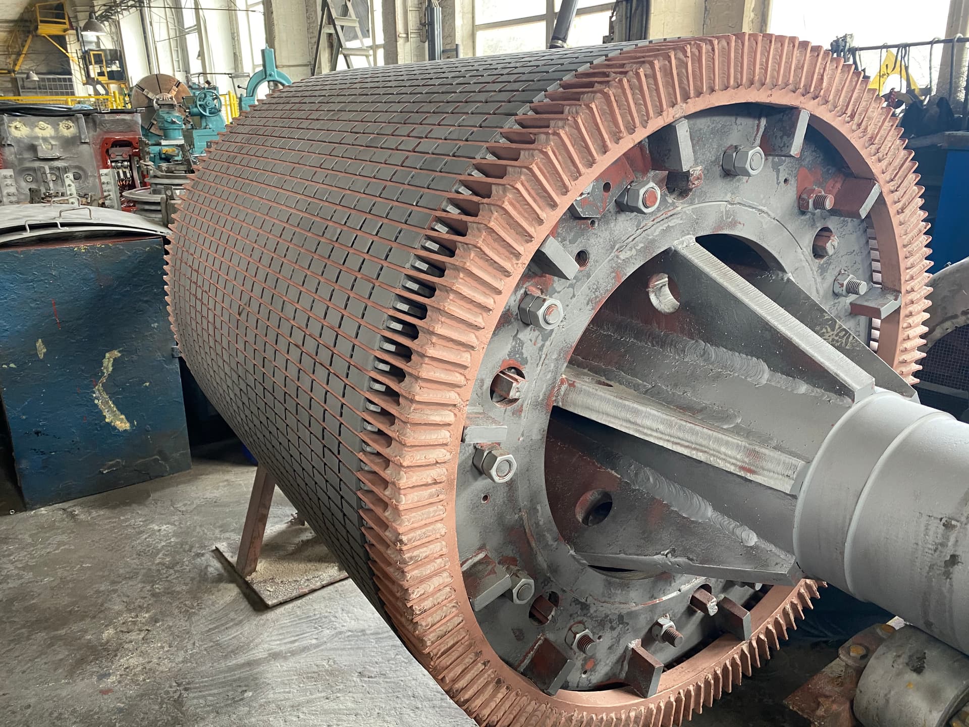
The rotor of an asynchronous motor

The rotor consists of:

  • the shaft;
  • the active-steel stack;
  • the rotor winding or squirrel cage;
  • the ventilation elements;
  • the balancing weights;
  • sometimes slip rings;
  • sometimes an external fan.

The main design types:

  1. 01Squirrel-cage rotor.
  2. 02Wound rotor.

Squirrel-cage rotor

The squirrel-cage rotor is the most common.

Conducting bars sit in the rotor slots, joined at the ends by short-circuiting rings.

Together they form what is known as the squirrel cage.

The bars may be made of:

  • cast aluminium;
  • copper;
  • copper alloy;
  • other special conductor materials.

ABB notes that the cages of high-voltage asynchronous motors may be made of copper, copper alloys or aluminium depending on the performance required.

Cast-aluminium rotor

On volume-produced motors the cage is often die-cast together with:

  • the bars;
  • the short-circuiting rings;
  • the ventilation vanes.

Advantages:

  • ease of manufacture;
  • the absence of a large number of brazed joints;
  • a relatively low production cost;
  • repeatability in series production.

Possible defects:

  • porosity;
  • incomplete filling of the slot;
  • cracks;
  • a broken bar;
  • a cracked ring;
  • local shrinkage;
  • inhomogeneity of the metal;
  • detachment of the vanes.

Rotor with a copper cage

Copper rotors may have:

  • bars inserted into the slots;
  • brazed short-circuiting rings;
  • welded joints;
  • a cast copper cage;
  • a special fabricated construction.

Advantages of copper:

  • lower electrical resistance;
  • the possibility of reducing losses;
  • better thermal conductivity;
  • high mechanical strength in the appropriate design.

The actual starting and running characteristics depend not only on the material but also on:

  • the slot shape;
  • the bar cross-section;
  • the slot depth;
  • the ring material;
  • the rotor current frequency;
  • the current-displacement effect.

Rotor slots

Slots may be:

  • open;
  • semi-closed;
  • closed;
  • deep;
  • double-cage;
  • trapezoidal;
  • oval;
  • specially profiled.

The slot shape affects:

  • the starting current;
  • the starting torque;
  • the breakdown torque;
  • the rated slip;
  • the losses;
  • the heating;
  • the noise;
  • the harmonics.

Deep-slot rotor

In a deep slot the current is displaced towards the outer part of the bar during starting.

The effective cross-section decreases and the resistance increases.

This can:

  • raise the starting torque;
  • limit the starting current;
  • improve the starting characteristics.

Once the motor is up to speed the rotor current frequency falls, the current spreads over more of the cross-section, and the losses decrease.

Double-cage rotor

It has two functional cages:

  • an outer one with higher resistance;
  • an inner one with lower resistance.

During starting most of the current flows in the outer cage, giving increased starting torque.

In normal running the current passes mainly into the inner cage, with lower losses.

Why rotor slots are often skewed

Rotor slots may be skewed relative to the shaft axis.

Skewing helps to:

  • reduce tooth pulsations;
  • lower the noise;
  • reduce the possibility of magnetic locking;
  • smooth the torque;
  • lower certain harmonic components.

But excessive or incorrect skew can affect torque and add losses.

Wound rotor

A wound rotor has a full polyphase winding, usually three-phase.

The winding ends are brought out to slip rings.

Through the brush gear the rotor can be connected to:

  • a starting rheostat;
  • a control resistance;
  • a special converter;
  • a control system.

Advantages:

  • high starting torque;
  • the ability to limit the starting current;
  • smooth acceleration;
  • the possibility of speed control in certain systems;
  • suitability for heavy starting duty.

Disadvantages:

  • a more complex construction;
  • slip rings;
  • brushes;
  • the need for regular maintenance;
  • greater losses;
  • higher cost;
  • additional possible faults.

Where wound-rotor motors are used

Traditional fields of application:

  • cranes;
  • hoists;
  • mine machinery;
  • mills;
  • crushers;
  • large conveyors;
  • excavators;
  • machines with heavy starting duty;
  • equipment with a large moment of inertia.

In many modern installations a squirrel-cage motor with a variable frequency drive takes over part of the wound rotor's role.

Wound-rotor motors nevertheless remain in service at a significant number of industrial sites.

Slip rings of a wound rotor

The rings are mounted on the shaft and insulated:

  • from one another;
  • from the shaft;
  • from the frame parts.

During repair the following are checked:

  • surface wear;
  • run-out;
  • ovality;
  • burning;
  • grooving;
  • the insulation;
  • the connection to the winding;
  • the condition of the brushes;
  • the brush pressure;
  • the brush holders;
  • dust extraction.

Air gap

The air gap is the distance between the inner surface of the stator and the outer surface of the rotor.

It affects:

  • the magnetising current;
  • the power factor;
  • the electromagnetic torque;
  • the noise;
  • the vibration;
  • the losses;
  • the sensitivity to eccentricity.

An excessively large gap:

  • increases the magnetising current;
  • worsens the power factor;
  • may reduce the overload capacity.

An excessively small gap:

  • raises the risk of the rotor rubbing the stator;
  • makes the machine sensitive to run-out;
  • complicates assembly;
  • may increase the influence of tooth harmonics.

The rotating magnetic field

Three-phase currents are displaced in time by approximately 120 electrical degrees.

The stator phase windings are also displaced in space.

The result is a magnetic field that rotates about the axis of the machine.

The direction of rotation depends on the phase sequence.

To reverse a three-phase motor it is usually enough to interchange any two supply phases.

Before changing the phases, confirm that reverse rotation is permitted by:

  • the pump;
  • the fan;
  • the gearbox;
  • the machine;
  • the lubrication system;
  • the threaded joints.

Synchronous speed

Synchronous speed is given by:

nₛ = 120f / P

where:

  • nₛ — synchronous speed, rpm;
  • f — supply frequency, Hz;
  • P — number of poles.

Or:

nₛ = 60f / p

where p is the number of pole pairs.

At 50 Hz:

Number of polesSynchronous speed
23000 rpm
41500 rpm
61000 rpm
8750 rpm
10600 rpm
12500 rpm

The actual rated speed of an asynchronous motor in motoring mode will be slightly lower.

What slip is

Slip is defined as:

s = (nₛ − n) / nₛ

where:

  • s — slip;
  • nₛ — synchronous speed;
  • n — rotor speed.

As a percentage:

s% = [(nₛ − n) / nₛ] × 100%

An example slip calculation

For a four-pole motor at 50 Hz:

  • synchronous speed — 1500 rpm;
  • actual speed — 1470 rpm.

Then:

s = (1500 − 1470) / 1500 = 0.02

or:

s = 2%

Slip in different regimes

With the rotor at standstill

n = 0, so:

s = 1, or 100%.

This is the starting condition.

At no load

The speed approaches synchronous and the slip is small.

At rated load

The slip increases to its rated value.

On overload

The slip rises further.

At synchronous speed

s = 0.

No working current is induced in the rotor, so the motor cannot produce steady motoring torque.

Above synchronous speed

The slip becomes negative and the machine may pass into generating mode.

Rotor current frequency

The frequency of the rotor current is given approximately by:

f₂ = s × f₁

where:

  • f₂ — rotor current frequency;
  • s — slip;
  • f₁ — stator frequency.

During starting:

s = 1, so the rotor frequency equals the supply frequency.

At rated load the slip is small, so the rotor current frequency is small too.

This matters for understanding:

  • the current-displacement effect;
  • the parameters of a deep-slot rotor;
  • the losses in the cage;
  • the diagnosis of broken bars.

How electromagnetic torque is created

The rotating stator field induces current in the rotor conductors.

The rotor currents create their own magnetic field.

The interaction of the stator and rotor fields forms the electromagnetic torque.

The magnitude of the torque depends on:

  • the voltage;
  • the frequency;
  • the slip;
  • the rotor resistance;
  • the reactance;
  • the magnetic flux;
  • the slot design;
  • the losses;
  • the saturation of the steel.

Torque-speed characteristic

The torque-speed characteristic shows how torque varies with speed or slip.

The main points:

  • the starting torque;
  • the minimum torque during acceleration;
  • the maximum or breakdown torque;
  • the rated torque;
  • the no-load point.

Starting torque

This is the torque with the rotor at standstill.

It must be enough to overcome:

  • the static resistance of the machine;
  • friction;
  • the load torque;
  • the inertia torque during acceleration.

Insufficient starting torque can lead to:

  • a prolonged start;
  • stator overheating;
  • rotor overheating;
  • the protection tripping;
  • the machine failing to start.

Starting current

On direct-on-line starting of a squirrel-cage motor the current may be several times the rated value.

The actual value depends on:

  • the motor design;
  • the rating;
  • the supply impedance;
  • the voltage;
  • the connection;
  • the rotor characteristics.

IEC 60034-12:2024 defines the parameters of eight starting-performance designs for single-speed three-phase squirrel-cage motors at 50 or 60 Hz with a rated voltage up to 1000 V, intended in particular for direct-on-line or star-delta starting.

Breakdown torque

Breakdown torque is the maximum torque a motor can develop under the given supply conditions without stalling.

If the load torque exceeds the breakdown torque:

  • the speed falls sharply;
  • the current rises;
  • the motor may stall;
  • the winding and rotor heat up rapidly.

Rated torque

Rated torque is given approximately by:

M = 9550P / n

where:

  • M — torque, N·m;
  • P — mechanical shaft power, kW;
  • n — speed, rpm.

A 100 kW motor running at 1480 rpm, for example, has a rated torque of approximately:

M = 9550 × 100 / 1480 ≈ 645 N·m

Overload capacity

Overload capacity shows by how much the maximum torque exceeds the rated torque.

It depends on the motor design and the voltage.

A drop in voltage substantially reduces the electromagnetic torque.

Simplified, the torque of an asynchronous motor in many regimes is roughly proportional to the square of the voltage.

A 10% drop in voltage may therefore reduce the available torque not by about 10% but by almost 19%.

Types of asynchronous motor by number of phases

  • three-phase;
  • single-phase;
  • special two-phase;
  • special polyphase.

Three-phase asynchronous motor

The most widespread in industry.

Advantages:

  • a natural rotating field;
  • a simple design;
  • long service life;
  • good efficiency;
  • no starting capacitor;
  • smoother torque;
  • a wide power range.

Single-phase asynchronous motor

A single-phase winding on its own does not create a proper starting rotating field.

The following are therefore used:

  • an auxiliary winding;
  • a starting capacitor;
  • a run capacitor;
  • a starting relay;
  • a centrifugal switch;
  • a shading coil on small motors.

The main types:

  • with a starting winding;
  • capacitor-start;
  • with a permanently connected capacitor;
  • with start and run capacitors;
  • shaded-pole.

Shaded-pole asynchronous motor

Used in low-power drives:

  • fans;
  • domestic appliances;
  • small pumps;
  • control equipment.

Advantages:

  • a very simple design;
  • low cost;
  • no capacitor.

Disadvantages:

  • low efficiency;
  • low starting torque;
  • limited power;
  • difficulty of reversing the direction of rotation.

Star and delta winding connections

A three-phase winding uses:

  • star;
  • delta;
  • special multi-parallel connections.

Star

In a star connection the phase voltage is √3 times lower than the line voltage.

Delta

In a delta connection the phase voltage equals the line voltage.

The connection must not be changed without regard to the rated phase voltage.

An example of 230/400 V marking

A motor with a 230/400 V nameplate normally means:

  • 230 V — delta;
  • 400 V — star.

Each phase winding is rated at approximately 230 V.

An example of 400/690 V marking

This normally means:

  • 400 V — delta;
  • 690 V — star.

Such a motor can be started star-delta from a 400 V supply if that suits its design and load.

Star-delta starting

The winding is first connected in star and switched to delta once the motor is up to speed.

This reduces:

  • the phase voltage;
  • the starting current;
  • the starting torque.

As a guide, the starting torque in star may be about one third of the direct-on-line torque in delta.

The arrangement is therefore unsuitable for machines with a high breakaway torque.

Direct-on-line starting

The motor is connected straight to the supply.

Advantages:

  • a simple circuit;
  • the maximum available starting torque;
  • few items of switchgear;
  • high reliability.

Disadvantages:

  • a large starting current;
  • voltage dip;
  • mechanical shock;
  • loading on the coupling and the driven machine.

Autotransformer starting

Reduces the voltage during starting.

It has been and still is used for large motors where direct-on-line starting is undesirable.

Reactor starting

A reactor is inserted in the stator circuit to limit the starting current.

The drawback is that the starting torque is reduced at the same time.

Soft starter

A soft starter controls the voltage by means of power semiconductor devices.

Advantages:

  • smooth acceleration;
  • reduced mechanical shock;
  • current limiting;
  • a soft stop in certain applications.

Limitations:

  • it does not provide full speed control in steady operation;
  • reducing the voltage reduces the torque;
  • it may generate harmonic components during starting.

Variable frequency drive

A variable frequency drive changes the supply frequency and voltage.

It allows you to:

  • control the speed;
  • provide a soft start;
  • limit the current;
  • control the torque;
  • save energy on pumps and fans;
  • implement braking;
  • automate the process.

Squirrel-cage asynchronous motors are widely used in variable-speed drives thanks to their availability, reliability and efficiency.

Points to note when running from a variable frequency drive

An inverter supply differs from a sinusoidal supply.

Additional factors are possible:

  • pulsed voltage;
  • a high rate of rise of the voltage front;
  • overvoltage at the terminals;
  • additional losses;
  • rotor heating;
  • acoustic noise;
  • currents through the bearings;
  • reduced self-cooling at low speed;
  • mechanical critical frequencies at high speed.

When retrofitting, check:

  • the winding insulation;
  • the cable length;
  • the drive's characteristics;
  • the need for a dU/dt filter;
  • the need for a sine filter;
  • electrical insulation of the bearings;
  • shaft earthing;
  • the permissible rotor speed;
  • the operation of the fan;
  • temperature monitoring.

V/f control

In simple scalar control the voltage is varied roughly in proportion to the frequency.

This helps to maintain the magnetic flux.

If full voltage is retained as the frequency falls:

  • the magnetic flux rises;
  • the steel saturates;
  • the current increases;
  • the motor overheats.

If the voltage is reduced too far:

  • the magnetic flux falls;
  • the available torque decreases.

Vector control

Vector control allows more independent control of:

  • the flux;
  • the torque;
  • the speed.

It can provide:

  • high torque at low speed;
  • precise regulation;
  • a fast dynamic response;
  • operation with or without a speed sensor.

Braking an asynchronous motor

The possible methods:

  • coasting;
  • dynamic braking;
  • DC injection braking;
  • plugging;
  • regenerative braking;
  • a mechanical brake.

When braking, take into account:

  • the thermal load;
  • the mechanical forces;
  • the permissible cycle rate;
  • the capability of the drive;
  • the braking resistor;
  • the safety of the driven machine.

Multi-speed asynchronous motors

The speed can be changed by switching the number of poles.

The following are used:

  • the Dahlander connection;
  • separate windings for different speeds;
  • combined arrangements.

Typical speed ratios:

  • 3000/1500;
  • 1500/750;
  • 1000/500;
  • others.

During repair it is especially important to reproduce exactly:

  • the connection;
  • the group direction;
  • the number of turns;
  • the pitch;
  • the leads;
  • the pole changing.

Low-voltage asynchronous motors

Broadly, these are motors with a rated voltage up to 1000 V in the context of many IEC standards.

Common voltages:

  • 230 V;
  • 400 V;
  • 500 V;
  • 660 V;
  • 690 V.

The rating may be:

  • fractions of a kilowatt;
  • tens of kilowatts;
  • hundreds of kilowatts;
  • more in some designs.

High-voltage asynchronous motors

They operate, for example, at:

  • 3 kV;
  • 6 kV;
  • 10 kV;
  • 11 kV;
  • other voltages.

They are used in:

  • power generation;
  • water supply;
  • metallurgy;
  • the mining industry;
  • the oil and gas sector;
  • large compressor stations;
  • flue-gas fans;
  • exhausters.

Features:

  • form-wound stator coils;
  • multi-layer main insulation;
  • mica materials;
  • vacuum-pressure impregnation;
  • partial discharge monitoring;
  • anti-corona coating;
  • a complex cooling system;
  • tighter air-gap requirements;
  • monitoring of shaft currents.

Explosion-proof asynchronous motors

Used in atmospheres where the following may be present:

  • explosive gases;
  • vapours;
  • dust;
  • combustible mixtures.

During repair the following must not be altered at will:

  • the flameproof gaps;
  • the fastenings;
  • the threads;
  • the seals;
  • the bearings;
  • the fan;
  • the materials;
  • the surface temperature;
  • the winding data;
  • the impregnation system.

Repair must be carried out in accordance with the documentation, the applicable standards and approved procedures.

Crane and metallurgical motors

They operate under:

  • frequent starting;
  • reversing;
  • braking;
  • overload;
  • intermittent periodic duty;
  • high temperature;
  • dust;
  • vibration.

They may have:

  • a squirrel-cage or wound rotor;
  • increased starting torque;
  • a special torque-speed characteristic;
  • a reinforced winding;
  • insulation class H;
  • thermal sensors;
  • a mechanical brake.

Submersible motors

They are used in:

  • borehole pumps;
  • drainage pumps;
  • sewage installations;
  • water-intake equipment.

Features:

  • a sealed construction;
  • operation in water or process liquid;
  • special cable entries;
  • moisture-resistant insulation;
  • leak-tightness monitoring;
  • sometimes filling with an internal liquid;
  • special bearings.

Hollow-shaft motors

Used on vertical pumps and special machinery.

They require:

  • control of the axial load;
  • accurate shaft geometry;
  • inspection of the thrust bearing;
  • verification of verticality;
  • correct adjustment of the pump rotor.

Motors with a brake

They have an electromagnetic or mechanical brake.

They are used:

  • in lifting gear;
  • positioning drives;
  • conveyors;
  • machine tools;
  • crane systems.

During repair the following are checked:

  • the braking torque;
  • the air gap;
  • the coil;
  • the rectifier;
  • the linings;
  • the springs;
  • the response time;
  • manual brake release.

Duty types

IEC 60034-1 defines the rated duty types and the main performance characteristics of rotating electrical machines.

Common duty types:

  • S1 — continuous;
  • S2 — short-time;
  • S3 — intermittent periodic;
  • S4 — intermittent periodic with starting;
  • S5 — with starting and electric braking;
  • S6 — continuous-operation periodic duty with varying load;
  • S7 — with starting and braking, no rest periods;
  • S8 — with periodic changes of speed and load;
  • S9 — non-periodic duty with overloads;
  • S10 — duty with discrete constant loads.

Duty S1

The motor runs long enough for the temperature to stabilise.

Typical examples:

  • pumps;
  • fans;
  • conveyors;
  • compressors.

Duty S2

Operation lasts a limited time, after which the motor cools down completely.

For example:

  • valve and gate actuators;
  • auxiliary machinery;
  • short process operations.

Duty S3

Periods of operation and rest repeat, but the effect of starting on heating is limited within the definition of the duty.

It is important to know the cyclic duration factor.

Duties S4 and S5

Suited to machines with frequent starting.

S5 additionally includes electric braking.

During repair, take into account:

  • rotor heating;
  • the starting currents;
  • the mechanical loads;
  • thermal ageing of the winding.

Cooling of asynchronous motors

The cooling system may be:

  • natural;
  • self-ventilated;
  • with a separate external fan;
  • with internal air circulation;
  • with an air-to-air heat exchanger;
  • with an air-to-water heat exchanger;
  • water-cooled;
  • a special closed system.

Self-ventilated motor

The fan is mounted on the shaft.

The airflow depends on the rotational speed.

When running from a variable frequency drive at low speed the cooling falls off, even though the motor may still be producing substantial torque.

This may call for a separate fan.

Separate ventilation

The fan is driven by its own motor.

Cooling does not depend on the speed of the main rotor.

It is used:

  • in variable-speed drives;
  • for prolonged running at low speed;
  • on large machines;
  • in heavy duty.

IP degree of protection

The IP code describes the protection of the enclosure against:

  • access to hazardous parts;
  • ingress of solid objects;
  • water.

Common versions:

  • IP23;
  • IP44;
  • IP54;
  • IP55;
  • IP56;
  • IP65;
  • IP66.

A higher IP does not automatically mean a better motor in every situation.

A more enclosed frame can impede heat removal, so the design has to be rated accordingly.

Mounting arrangement

Motors can be mounted:

  • on feet;
  • on a flange;
  • on a small flange;
  • vertically;
  • horizontally;
  • in combination.

Common designations:

  • IM B3;
  • IM B5;
  • IM B35;
  • IM B14;
  • IM V1;
  • IM V3;
  • others.

When changing the mounting position, check:

  • the bearings;
  • the lubricant;
  • the axial load;
  • the drainage;
  • the ventilation;
  • the protection against water;
  • the fixings.

Energy performance

The main figures:

  • efficiency;
  • the power factor;
  • rated current;
  • the losses;
  • the slip;
  • temperature;
  • the starting current;
  • starting and maximum torque.

Efficiency

Efficiency:

η = P₂ / P₁

where:

  • P₂ — mechanical shaft power;
  • P₁ — active electrical power drawn from the supply.

The losses comprise:

  • stator copper losses;
  • rotor losses;
  • the core losses;
  • mechanical losses;
  • ventilation losses;
  • additional load losses.

Energy-efficiency classes

IEC 60034-30-1:2025 sets energy-efficiency classes for defined single-speed motors rated for a sinusoidal 50 or 60 Hz supply. The scope of that edition covers motors from 0.12 to 1000 kW, 50 to 1000 V, with 2, 4, 6 or 8 poles, under the conditions the standard specifies.

Common classes:

  • IE1 — Standard Efficiency;
  • IE2 — High Efficiency;
  • IE3 — Premium Efficiency;
  • IE4 — Super Premium Efficiency.

Other standards and regulatory systems may also apply additional classes for special types of machine.

Can rewinding raise the IE class?

An ordinary rewind does not guarantee a higher energy-efficiency class.

Efficiency depends on:

  • the core design;
  • the grade of steel;
  • the stack length;
  • the slot geometry;
  • the air gap;
  • the rotor cage;
  • the fan;
  • the amount of copper;
  • the bearing losses;
  • the harmonic losses.

A poor rewind can, on the contrary, reduce efficiency.

Power factor

The power factor shows the ratio of active to apparent power.

An asynchronous motor needs magnetising current.

The power factor is therefore:

  • low at no load;
  • higher as the load increases;
  • at its rated value near the design load.

Why a heavily under-loaded motor should not be run for long periods

The possible consequences:

  • a low power factor;
  • wasteful losses;
  • low system efficiency;
  • higher capital cost;
  • sub-optimal operation of the drive.

Replacing the motor with a smaller one does, however, require checking:

  • the starting torque;
  • overload;
  • the duty type;
  • the margin for process variations.

The nameplate

The nameplate may state:

  • the manufacturer;
  • the type;
  • the serial number;
  • the rating;
  • the voltage;
  • the current;
  • the frequency;
  • the number of phases;
  • the connection;
  • the speed;
  • efficiency;
  • cos φ;
  • the duty type;
  • the insulation class;
  • the degree of protection;
  • the mounting arrangement;
  • the ambient temperature;
  • the altitude above sea level;
  • the IE class;
  • the bearings;
  • the mass;
  • explosion-protection requirements;
  • data for inverter operation.

How to determine the number of poles from the speed

At 50 Hz, approximately:

  • about 3000 rpm — 2 poles;
  • about 1500 — 4;
  • about 1000 — 6;
  • about 750 — 8;
  • about 600 — 10;
  • about 500 — 12.

The actual speed is slightly lower because of slip.

Advantages of asynchronous motors

  • a simple design;
  • no commutator in the squirrel-cage version;
  • high reliability;
  • low cost;
  • ready availability;
  • a wide power range;
  • the ability to start direct-on-line;
  • the ability to use variable frequency control;
  • repairability;
  • suitability for harsh conditions;
  • a wide choice of protective versions;
  • a good power-to-weight ratio;
  • high efficiency when correctly matched to the duty.

Disadvantages

  • a large starting current on direct-on-line starting;
  • speed that depends on load;
  • consumption of reactive power;
  • a low power factor at no load;
  • the difficulty of smooth control without a drive;
  • rotor heating with frequent starting;
  • the risk of bearing currents on an inverter supply;
  • reduced self-cooling at low speed;
  • substantial mechanical loads at starting.

Typical faults of asynchronous motors

They fall broadly into:

  • electrical;
  • insulation;
  • magnetic;
  • rotor;
  • mechanical;
  • thermal;
  • ventilation;
  • installation;
  • operational.

Interturn short circuit

It occurs between adjacent turns of the same coil.

Causes:

  • ageing of the enamel;
  • overheating;
  • vibration;
  • damage during laying;
  • pulsed voltage;
  • contamination;
  • poor impregnation;
  • frequent starting.

Consequences:

  • circulating current in the shorted turns;
  • local overheating;
  • further destruction of the insulation;
  • a phase-to-phase short circuit;
  • breakdown to the frame.

Phase-to-phase short circuit

It can occur:

  • in the slot;
  • in the end windings;
  • at a joint;
  • in the terminal box.

Causes:

  • damaged phase-to-phase insulation;
  • vibration;
  • contamination;
  • overvoltage;
  • incorrect laying;
  • thermal ageing.

Short circuit to the frame

A live part makes contact with the earthed core or frame.

Causes:

  • damaged slot insulation;
  • sharp slot edges;
  • contamination;
  • moisture;
  • breakdown of a lead;
  • mechanical movement of the coil.

Open phase or open parallel branch

Symptoms:

  • current unbalance;
  • reduced torque;
  • overheating;
  • the noise;
  • starting problems;
  • increased vibration.

Where the damage occurs:

  • a lead;
  • a brazed joint;
  • a link;
  • a terminal;
  • a coil-to-coil connection.

Running on two phases

If one phase is lost the motor may:

  • fail to start;
  • keep turning under a light load;
  • draw increased currents in the other phases;
  • overheat rapidly.

The cause may lie not in the motor but in:

  • a fuse;
  • the contactor;
  • the cable;
  • a terminal;
  • the circuit breaker;
  • the supply network.

Voltage unbalance

Even a relatively small voltage unbalance can produce a much larger current unbalance.

Consequences:

  • overheating;
  • torque pulsations;
  • vibration;
  • a shorter insulation life;
  • increased loading of the rotor.

Reduced voltage

It can cause:

  • reduced torque;
  • a prolonged start;
  • a rise in current under load;
  • overheating;
  • the motor stalling.

Increased voltage

It can cause:

  • excessive magnetic flux;
  • saturation of the steel;
  • an increase in no-load current;
  • heating of the core;
  • the noise;
  • increased stress on the insulation.

Broken rotor bars

Symptoms:

  • reduced starting torque;
  • torque pulsations;
  • vibration;
  • the noise;
  • increased slip;
  • unstable current;
  • local heating of the rotor.

Causes:

  • frequent starting;
  • large thermal cycles;
  • casting defects;
  • metal fatigue;
  • overload;
  • jamming of the driven machine.

Cracked short-circuiting ring

It can look much like a broken bar.

It is especially dangerous at:

  • the joint with the bar;
  • a change of section;
  • a casting defect;
  • a brazed or welded seam.

Wound-rotor defects

  • interturn short circuits;
  • breakdown to the frame;
  • an open winding;
  • disturbed connections;
  • burning of the slip rings;
  • uneven brush contact;
  • an open rheostat circuit;
  • unbalance of the external resistances.

Damage to the stator active steel

Causes:

  • burning out the winding with an open flame;
  • an excessive burn-out temperature;
  • mechanical destruction of the laminations;
  • rotor rubbing;
  • a short circuit between laminations;
  • welding the stack without control.

Symptoms:

  • increased no-load current;
  • local hot spots;
  • asymmetric heating;
  • increased losses;
  • humming.

Uneven air gap

Causes:

  • worn bearings;
  • worn fits;
  • misaligned end shields;
  • a bent shaft;
  • a distorted frame;
  • an eccentric core;
  • incorrect assembly.

Consequences:

  • one-sided magnetic pull;
  • vibration;
  • the noise;
  • current harmonics;
  • the risk of the rotor rubbing.

Bearing faults

  • fatigue spalling;
  • contamination;
  • insufficient lubrication;
  • excess grease;
  • electrical erosion;
  • corrosion;
  • turning of the rings;
  • misalignment;
  • an incorrect clearance.

Motor overheating

The possible causes:

  • overload;
  • reduced voltage;
  • phase unbalance;
  • frequent starting;
  • contaminated ventilation;
  • the wrong fan;
  • a high ambient temperature;
  • faulty bearings;
  • an interturn short circuit;
  • a poor rewind;
  • rotor damage;
  • a high no-load current;
  • incorrect drive settings.

Increased vibration

Causes:

  • rotor imbalance;
  • misalignment;
  • a soft foot;
  • a loose foundation;
  • a bearing defect;
  • a bent shaft;
  • eccentricity;
  • a broken rotor bar;
  • resonance;
  • a coupling defect;
  • misaligned end shields.

Increased noise

It may be:

  • electromagnetic;
  • mechanical;
  • aerodynamic;
  • bearing-related;
  • resonant.

It is important not to draw conclusions by ear alone.

The motor does not start

Check:

  • that all phases are present;
  • the voltage level;
  • the connection;
  • the contactor;
  • the protection;
  • the interlocks;
  • mechanical jamming;
  • the bearings;
  • an open winding;
  • the condition of the rotor;
  • the load;
  • the drive settings.

The motor starts off-load but will not start the driven machine

The possible causes:

  • insufficient starting torque;
  • reduced voltage;
  • star connected by mistake instead of delta;
  • too great a load;
  • jamming of the driven machine;
  • broken bars;
  • a faulty wound-rotor rheostat;
  • incorrect soft-start settings;
  • an excessively short ramp;
  • a rewinding error.

Increased no-load current

Causes:

  • the wrong number of turns;
  • a reduced winding length or pitch;
  • an excessively reduced air gap;
  • damage to the core;
  • increased voltage;
  • the wrong frequency;
  • winding unbalance;
  • an incorrect connection;
  • rotor rubbing.

Low insulation resistance

Causes:

  • moisture;
  • dust;
  • the lubricant;
  • condensation;
  • ageing;
  • damaged leads;
  • a contaminated terminal box;
  • partial breakdown;
  • poor impregnation.

Low resistance does not always mean a full rewind is needed. First establish the cause and whether cleaning and drying are possible.

Diagnostic methods

Visual inspection

Check:

  • the winding;
  • the end windings;
  • the bracing;
  • the leads;
  • the terminals;
  • traces of overheating;
  • contamination;
  • the bearings;
  • the fan;
  • the rotor;
  • the core;
  • the slip rings.

Insulation resistance measurement

It allows the condition of the insulation to be assessed to the frame and between electrically separate circuits.

Take into account:

  • the temperature;
  • the humidity;
  • the rated voltage;
  • the duration of the measurement;
  • the history of previous values.

Absorption ratio and polarisation index

They help to assess:

  • contamination;
  • the humidity;
  • the polarisation properties of the insulation.

On small low-voltage windings the interpretation may be limited by the low capacitance and the rapid settling of the reading.

Measurement of phase resistance

It reveals:

  • an open circuit;
  • a poor joint;
  • unbalance;
  • an error in the number of turns;
  • different lengths of parallel branches;
  • a faulty contact.

The results must be corrected to a common temperature.

Interturn surge test

It compares the response of phases or coils to a short impulse.

It helps to reveal:

  • an interturn short circuit;
  • weakened insulation;
  • connection errors;
  • a difference in the number of turns.

High-voltage withstand test

It verifies the strength of the insulation to the frame and between electrical circuits.

It does not reveal every interturn defect, so it does not replace the surge test.

Partial discharge monitoring

Especially important for high-voltage windings.

It allows assessment of:

  • internal voids;
  • delamination;
  • defects in the slot portion;
  • the condition of the corona protection;
  • ageing of the insulation.

Core testing

The possible methods:

  • ring flux (loop) test;
  • thermal imaging;
  • EL CID;
  • local test methods.

The purpose:

  • to reveal interlaminar short circuits;
  • local hot spots;
  • damage left after removing the winding.

Motor current analysis

Motor Current Signature Analysis can be used to detect:

  • broken bars;
  • eccentricity;
  • unbalance;
  • certain mechanical defects.

Diagnosis of broken rotor bars often relies on analysing the slip-related sidebands, but the accuracy depends on the load and the operating regime.

Vibration diagnostics

It allows assessment of:

  • imbalance;
  • misalignment;
  • a soft foot;
  • the bearings;
  • mechanical looseness;
  • resonance;
  • electromagnetic forces;
  • rotor defects.

Thermal imaging

It reveals:

  • overheated bearings;
  • terminal unbalance;
  • hot joints;
  • local heating of the frame;
  • contamination of the cooling;
  • overload.

Air-gap measurement

It is measured at several positions.

On large machines the following may be used:

  • mechanical feeler gauges;
  • special sensors;
  • displacement measurement;
  • electromagnetic methods.

Stages of asynchronous motor repair

  1. 01Intake and recording of completeness.
  2. 02Analysis of the fault history.
  3. 03External inspection.
  4. 04Initial electrical measurements.
  5. 05Vibration measurement, if starting is safe.
  6. 06Dismantling.
  7. 07Marking the position of parts.
  8. 08Removal of the rotor.
  9. 09Fault detection on the bearings.
  10. 10Shaft measurement.
  11. 11Inspection of the end shields.
  12. 12Stator testing.
  13. 13Rotor testing.
  14. 14Core testing.
  15. 15Recording the winding data.
  16. 16Removal of the damaged winding.
  17. 17Cleaning.
  18. 18Restoration of the mechanical parts.
  19. 19Rewinding.
  20. 20Insulating and connecting.
  21. 21Electrical tests before impregnation.
  22. 22Drying.
  23. 23Impregnation.
  24. 24Curing.
  25. 25Finishing.
  26. 26Rotor balancing.
  27. 27Fitting the bearings.
  28. 28Assembly.
  29. 29Adjustment of the axial position.
  30. 30No-load test.
  31. 31Monitoring of temperature, current and vibration.
  32. 32Issuing the test report.

Recording the winding data

Before removing the winding, record:

  • the number of slots;
  • the number of poles;
  • the number of phases;
  • the pitch;
  • the number of turns;
  • the wire diameter;
  • the number of parallel conductors;
  • the number of branches;
  • the connection;
  • the winding direction;
  • the coil distribution;
  • the leads;
  • the end-winding dimensions;
  • the slot insulation;
  • the bracing;
  • the wedges;
  • the sensors;
  • the mass of copper.

Why you cannot copy the old wire diameter alone

You have to restore:

  • the copper cross-section;
  • the number of turns;
  • the number of parallels;
  • the connection;
  • the turn length;
  • the slot fill;
  • the insulation class;
  • the phase resistance.

The old wire may be:

  • deformed;
  • overheated;
  • partly stripped of enamel;
  • incorrectly specified by a previous repair.

Removing the old winding

Incorrect burn-out can damage the interlaminar insulation of the core.

The following are therefore controlled:

  • the temperature;
  • the duration;
  • the uniformity of heating;
  • the condition of the steel;
  • distortion of the frame.

An open, uncontrolled flame is dangerous to the core.

Rewinding the stator

The main operations:

  • preparing the slots;
  • laying the slot insulation;
  • making the coils;
  • laying the wire;
  • fitting the phase-to-phase insulation;
  • connecting the groups;
  • forming the end windings;
  • bracing;
  • fitting the wedges;
  • fitting the sensors;
  • testing;
  • impregnation.

Impregnation

The impregnating material:

  • fills the voids;
  • strengthens the winding;
  • improves heat transfer;
  • protects against moisture;
  • reduces movement of the conductors;
  • increases resistance to vibration.

The possible processes:

  • dipping;
  • vacuum impregnation;
  • vacuum-pressure impregnation;
  • trickle impregnation;
  • flood coating.

Squirrel-cage rotor repair

It may include:

  • cleaning;
  • checking the bars;
  • fault detection on the rings;
  • restoring brazed joints;
  • replacing copper bars;
  • repairing the short-circuiting rings;
  • restoring the ventilation elements;
  • shaft repair;
  • checking the stack;
  • balancing.

Repairing a cast-aluminium cage is more difficult and depends on:

  • the location of the defect;
  • the material;
  • the rating;
  • the design;
  • the technology available.

Wound-rotor repair

It includes:

  • fault detection on the winding;
  • recording the winding data;
  • making the coils;
  • slot insulation;
  • laying;
  • bracing;
  • impregnation;
  • repair of the slip rings;
  • repair of the brush gear;
  • balancing;
  • electrical tests.

Rotor balancing

Required after:

  • replacing or repairing the shaft;
  • repairing the cage;
  • replacing the fan;
  • repairing a wound-rotor winding;
  • any significant mechanical work;
  • replacing balancing elements;
  • finding increased imbalance.

Tests after repair

They may include:

  • insulation resistance;
  • the absorption ratio;
  • the polarisation index;
  • phase resistance;
  • the interturn surge test;
  • the high-voltage withstand test;
  • verification of the direction of rotation;
  • no-load running;
  • current measurement;
  • vibration monitoring;
  • temperature monitoring;
  • checking the bearings;
  • speed measurement;
  • checking the wound rotor;
  • partial discharge monitoring;
  • load tests where facilities allow.

Why a motor may run worse after rewinding

Causes:

  • the wrong number of turns;
  • the wrong pitch;
  • a different connection;
  • a reduced copper cross-section;
  • longer end windings;
  • an error in group polarity;
  • incorrect connection of parallel branches;
  • damage to the core;
  • an incorrect air gap;
  • an unsuitable fan;
  • poor impregnation;
  • poor-quality joints;
  • mechanical misalignment.

Typical repair mistakes

  1. 01Removing the old winding without recording the data.
  2. 02Identifying the wire by its outside diameter alone.
  3. 03Arbitrarily changing the number of turns.
  4. 04Reducing the copper cross-section.
  5. 05The wrong winding pitch.
  6. 06Wrongly connected groups.
  7. 07Ignoring parallel branches.
  8. 08Uncontrolled burn-out of the core.
  9. 09Omitting the core test.
  10. 10Damaging the slots during removal.
  11. 11Inadequate slot insulation.
  12. 12Weak bracing.
  13. 13Missing phase-to-phase insulation.
  14. 14Poor impregnation.
  15. 15Impregnating a damp winding.
  16. 16Incorrect curing.
  17. 17Fitting unsuitable bearings.
  18. 18Assembling onto worn fits.
  19. 19Omitting balancing.
  20. 20The wrong fan.
  21. 21Misaligned end shields.
  22. 22Omitting the air-gap check.
  23. 23Omitting the surge test.
  24. 24Testing with a megohmmeter only.
  25. 25Ignoring the cause of the original failure.
  • What not to do
  • Do not change the winding data without calculation
  • Do not burn out the stator with an open flame
  • Do not use whatever copper wire is at hand
  • Do not reduce the number of turns to make winding easier
  • Do not increase the air gap by machining without calculation
  • Do not substitute the cage material arbitrarily
  • Do not fit the rotor without balancing after significant repair
  • Do not start the motor without checking the connection
  • Do not stop at an insulation resistance measurement
  • Do not assume every case of heating comes from the winding

The cause may lie in:

  • the bearings;
  • the load;
  • the ventilation;
  • the voltage;
  • the driven machine;
  • the alignment;
  • the variable frequency drive.

Diagnostic table

SymptomPossible causeWhat to check
The motor does not startA phase is missingThe voltage and the contactor
Hums but does not turnJamming or loss of a phaseThe shaft and the supply
Long starting timeLow voltageThe supply and the load
Low torqueIncorrect connectionStar/delta
All phases overheatOverloadThe current and the driven machine
One phase overheatsUnbalance or a winding defectThe phase resistances
High no-load currentToo few turns or a steel defectThe winding and the core
Different phase currentsVoltage or winding unbalanceThe voltages and the resistances
Torque pulsationsA broken barCurrent analysis
Hum at twice the frequencyElectromagnetic asymmetryThe air gap and the supply
1× vibrationImbalanceThe rotor
Axial vibrationMisalignmentThe alignment
A bearing overheatsLubricant or fitThe bearing assembly
Low insulation resistanceMoisture or contaminationThe winding
The protection trips on startingExcessive current or a short circuitThe settings and the motor
The motor runs more slowlyOverload or a rotor defectThe slip
It gets hot at low speedInsufficient coolingA separate fan
Bearings are being destroyedShaft currentsThe drive and the earthing
Noise increased after repairThe air gap or the windingThe geometry
The rotor touches the statorThe bearings, shaft or end shieldsAir gap

Practical cases

After rewinding, the motor has an increased no-load current

Check:

  • the number of turns;
  • the pitch;
  • the connection;
  • the group direction;
  • the voltage;
  • the frequency;
  • the core;
  • the air gap;
  • rotor rubbing;
  • the phase symmetry.

The motor runs well off-load but overheats in service

Check:

  • the actual load;
  • the current;
  • the slip;
  • the ventilation;
  • the copper cross-section;
  • the length of the end windings;
  • the rotor;
  • the voltage;
  • the alignment;
  • the bearings.

The motor will not start after the star-delta changeover

The possible causes:

  • an incorrect sequence of leads;
  • wrongly connected phases;
  • changeover too early;
  • too heavy a load;
  • a voltage drop;
  • a faulty contactor;
  • an incorrect nameplate or supply.

The motor runs on a mains supply, but the insulation fails on an inverter

Check:

  • the impulse withstand;
  • the cable length;
  • the voltage fronts;
  • the overvoltage;
  • the switching frequency;
  • the filters;
  • the earthing;
  • the quality of impregnation;
  • the condition of the first turns of the phase.

Bearings began to fail after switching to a variable frequency drive

The likely causes:

  • shaft voltage;
  • high-frequency currents;
  • incorrect screening;
  • the absence of an insulated bearing;
  • the absence of shaft earthing;
  • current through the driven machine.

The motor has increased slip

Check:

  • overload;
  • the voltage;
  • broken bars;
  • the cage resistance;
  • the frequency;
  • an incorrect rewind;
  • mechanical losses;
  • the bearings.

How to select an asynchronous motor

  • Step 1. Determine the power of the driven machine
  • Step 2. Determine the required speed
  • Step 3. Determine the load torque
  • Step 4. Assess the starting torque
  • Step 5. Determine the moment of inertia
  • Step 6. Establish the number of starts
  • Step 7. Choose the duty type
  • Step 8. Determine the voltage and frequency
  • Step 9. Choose the starting method
  • Step 10. Determine the need for speed control
  • Step 11. Choose the cooling system
  • Step 12. Determine the degree of protection
  • Step 13. Allow for temperature and altitude
  • Step 14. Check the explosion hazard
  • Step 15. Choose the mounting arrangement
  • Step 16. Check the bearing loads
  • Step 17. Choose the energy-efficiency class
  • Step 18. Provide protection and sensors
  • Step 19. Verify operation with a drive
  • Step 20. Check the availability of service support

Protection of an asynchronous motor

It may include:

  • short-circuit protection;
  • overload;
  • loss of a phase;
  • unbalance;
  • earth faults;
  • locked rotor;
  • a prolonged start;
  • winding overheating;
  • bearing overheating;
  • under- or overvoltage;
  • exceeding the permitted number of starts;
  • vibration;
  • a fall in insulation resistance.

Temperature sensors

The following are used:

  • RTD;
  • Pt100;
  • Pt1000;
  • PTC;
  • NTC;
  • thermocouples;
  • bimetallic contacts.

They may be fitted:

  • in the winding;
  • in the end shields;
  • in the bearing shells;
  • in the airflow;
  • in the heat exchanger.

Anti-condensation heaters

While the motor is idle the heater keeps it slightly above ambient temperature.

This reduces the risk of:

  • condensation;
  • dampening of the insulation;
  • corrosion;
  • a fall in insulation resistance.

The heater must not run at the same time as the motor unless the circuit provides for it.

Maintenance

Regularly check

  • the currents;
  • the voltage;
  • the temperature;
  • the vibration;
  • the noise;
  • the condition of the bearings;
  • the ventilation;
  • contamination;
  • the terminals;
  • the fastenings;
  • the alignment;
  • the condition of the cable;
  • insulation resistance;
  • the number of starts.

While the motor is stopped

  • clean the ventilation ducts;
  • check the fan;
  • tighten the terminals;
  • inspect the seals;
  • check the lubricant;
  • check the foundation;
  • check the coupling;
  • correct any soft foot.

What a repair report should contain

  • the motor data;
  • the works serial number;
  • the rating;
  • the voltage;
  • the current;
  • the speed;
  • the connection;
  • the number of poles;
  • the winding data;
  • the insulation materials;
  • the wire grade;
  • the results of the core test;
  • the rotor data;
  • the shaft measurements;
  • the bearing data;
  • balancing;
  • the phase resistances;
  • insulation resistance;
  • the surge test;
  • the high-voltage withstand test;
  • the no-load current;
  • the vibration;
  • the temperature;
  • the direction of rotation;
  • the conclusion.

Frequently asked questions

What is an asynchronous motor?

It is an AC motor whose rotor turns at a speed different from that of the stator's magnetic field.
Why is it called an induction motor?

Because the current in the rotor is induced by the stator's magnetic field.

Which rotor is used most often?

The squirrel-cage rotor.

What is a squirrel cage?

A system of rotor bars joined by short-circuiting rings.

What is a wound rotor?

A rotor with a polyphase winding brought out to slip rings.

Why is slip necessary?

Without slip no rotor current would be induced and no motoring torque would be produced.

Can the rotor turn at synchronous speed?

Not in steady motoring operation.

What determines the synchronous speed?

The frequency and the number of poles.

How do you reverse the direction of rotation?

Interchange two phases, if the driven machine permits it.

How does star differ from delta?

In the phase voltage and the current characteristics.

Can a motor run permanently in star?

Only if that connection matches the rated voltage of the winding.

Why is the starting current so high?

At standstill the slip equals unity, and the electromagnetic condition resembles a transformer with a short-circuited secondary.

How does a soft starter differ from a variable frequency drive?

A soft starter mainly controls the voltage during starting, whereas a drive changes the frequency and can control the speed.

Can any motor be fed from a drive?

You have to check the insulation, the cooling, the speed, the bearings and the impulse voltage.

Why does a motor get hot at low speed?

The shaft-mounted fan produces less airflow.

What is IE3?

The Premium Efficiency energy class in the relevant IEC system.

Will an old motor become IE3 after rewinding?

Not necessarily. Efficiency testing is required, and the design may not allow that class to be reached.

Why does an asynchronous motor hum?

Because of electromagnetic forces, supply defects, the air gap, the bearings, the rotor, the fan or mechanical resonance.

Why do the phase currents differ?

Because of unbalance in the voltages, the winding or the connections, or rotor defects.

Is a megohmmeter check of a motor enough?

No. A megohmmeter does not reveal every interturn, rotor or mechanical defect.

Why does a motor draw more current after repair?

Possible reasons are an incorrect number of turns, a damaged core, an incorrect air gap, the connection, mechanical friction or increased load.

Services of ELEKTROPROMREMONT LLC

ELEKTROPROMREMONT LLC carries out comprehensive repair and testing of asynchronous electric motors of various duties and ratings.

The scope of work may include:

  • intake diagnostics;
  • dismantling;
  • fault detection;
  • recording the winding data;
  • stator winding tests;
  • squirrel-cage rotor testing;
  • fault detection on a wound rotor;
  • repair of the slip rings;
  • repair of the brush gear;
  • checking the active steel;
  • core testing;
  • stator rewinding;
  • wound-rotor rewinding;
  • manufacture of stator coils;
  • manufacture of rotor coils;
  • replacement of slot insulation;
  • restoration of phase-to-phase insulation;
  • bracing;
  • vacuum impregnation;
  • vacuum-pressure impregnation;
  • repair of the squirrel cage;
  • replacement of copper bars;
  • repairing the short-circuiting rings;
  • shaft repair;
  • restoration of bearing seats;
  • repair of the end shields;
  • bearing replacement;
  • fitting of insulated bearings;
  • dynamic balancing;
  • fan restoration;
  • repair of the cooling system;
  • repair of heat exchangers;
  • fitting of temperature sensors;
  • insulation resistance measurement;
  • measurement of phase resistances;
  • interturn surge tests;
  • the high-voltage withstand test;
  • partial discharge monitoring;
  • no-load testing;
  • current measurement;
  • speed monitoring;
  • temperature tests;
  • vibration monitoring;
  • preparation of the repair report.

Conclusion

An asynchronous motor is an electrical machine in which the rotating stator field induces currents in the rotor and creates electromagnetic torque.

Its principal design feature is the difference between:

  • the synchronous speed of the field;
  • the actual speed of the rotor.

That difference is called slip and is a necessary condition for producing torque.

The main advantages of asynchronous motors:

  • a simple and reliable design;
  • a wide power range;
  • no commutator in the squirrel-cage version;
  • the ability to start direct-on-line;
  • suitability for variable frequency control;
  • repairability;
  • ready availability.

The life of a motor does not, however, depend on the winding alone.

The following have to be kept under control:

  1. 01The stator core.
  2. 02The stator winding.
  3. 03The squirrel-cage or wound rotor.
  4. 04The air gap.
  5. 05The shaft.
  6. 06The bearings.
  7. 07The cooling system.
  8. 08The balancing.
  9. 09The supply.
  10. 10The protection.
  11. 11The alignment with the driven machine.
  12. 12The operating conditions.

The guiding principle of a good repair:

An asynchronous motor has to be restored as a single electromagnetic, insulation, thermal and mechanical system, not as a set of separate parts.

Rewinding without testing the core, replacing bearings without checking the fits, or repairing a rotor without balancing do not deliver a predictable service life.

A sound repair must include:

  • identifying the root cause of the fault;
  • full fault detection;
  • exact reproduction of the winding data;
  • testing of the active steel;
  • rotor repair;
  • restoration of the mechanical geometry;
  • correct impregnation;
  • balancing;
  • electrical and mechanical tests;
  • documentation of the results.

Disclaimer

This article is of a general informational nature.

The specific choice of motor, starting method, connection, load, cooling system, variable frequency drive settings, protection, winding data and repair technology must be determined on the basis of:

  • the manufacturer's documentation;
  • the works drawings;
  • the nameplate;
  • the electromagnetic design;
  • the actual operating regime;
  • the characteristics of the driven machine;
  • the supply network;
  • the ambient conditions;
  • explosion-protection requirements;
  • the applicable standards;
  • the results of professional diagnostics.

Without engineering justification it is not permissible to:

  • change the number of turns;
  • change the copper cross-section;
  • change the winding connection;
  • change the number of poles;
  • increase the speed;
  • change the rotor design;
  • change the air gap;
  • convert the motor to a different voltage;
  • use a variable frequency drive outside the permissible range;
  • change the cooling system;
  • replace explosion-proof components with standard ones.

Work on high-voltage, explosion-proof, crane and metallurgical, submersible and other special motors must be carried out by qualified personnel using appropriate equipment, controlled processes and calibrated measuring instruments.

Important disclaimer

This material is for informational purposes. The values, diagnostic methods, scope of work and recommendations given here are general and do not replace the manufacturer’s technical documentation. The final decision for a specific machine is made from its own diagnostics and inspection, taking into account its type, power, design, duty, operating history and applicable standards.

Need to repair an asynchronous electric motor?

We will carry out fault detection, stator and rotor testing, rewinding, mechanical repair, balancing and verification tests to suit the design of your machine.

Get a consultation