Electric motor repair — the technological process
  1. // ELEKTROPROMREMONT
  2. Repair process

Electric motor repair — the technological process

Repairing an electric motor is not simply a matter of replacing bearings or rewinding a burnt-out winding. A proper repair means establishing the root cause of the damage, checking every electrical and mechanical assembly, restoring their parameters, correctly reassembling the machine and carrying out verification tests.

If only the visible consequence of the failure is eliminated without finding its cause, the motor may fail again after just a few hours, days or months of operation.

For example, a stator winding may have burnt out not because of poor-quality insulation, but because of:

  • overload of the driven machine;
  • voltage unbalance between phases;
  • running on two phases;
  • contamination of the cooling system;
  • a seized bearing;
  • an uneven air gap;
  • a defect of the squirrel-cage rotor;
  • frequent starts;
  • incorrectly set protection;
  • an unsuitable variable frequency drive regime.

If this cause is not eliminated after rewinding, the new winding may fail again.

A professional motor repair must therefore answer three main questions:

  1. 01What exactly is damaged?
  2. 02Why did the damage occur?
  3. 03What work and checks are needed for the motor to run reliably after the repair?

The short answer

A typical repair of an industrial electric motor includes:

  1. 01Receiving and identifying the equipment.
  2. 02Recording the completeness and external condition.
  3. 03Collecting information about the failure and the operating conditions.
  4. 04Incoming electrical measurements.
  5. 05Measuring the insulation resistance and the windings.
  6. 06Preliminary mechanical diagnostics.
  7. 07Marking the relative position of the parts.
  8. 08Disassembling the motor.
  9. 09Cleaning and washing the parts.
  10. 10A complete inspection of the stator.
  11. 11A complete inspection of the rotor.
  12. 12Checking the shaft, the bearing seats and the end shields.
  13. 13Checking the bearings, the fan, the coupling and the seals.
  14. 14Agreeing the scope of the repair.
  15. 15Restoring or rewinding the windings.
  16. 16Repairing the mechanical assemblies.
  17. 17Repairing the rotor.
  18. 18Restoring the fitting surfaces.
  19. 19Balancing the rotor.
  20. 20Assembling the motor.
  21. 21Adjusting the air gap and the axial position.
  22. 22Electrical testing.
  23. 23No-load testing.
  24. 24Monitoring the current, vibration, noise and temperature.
  25. 25Preparing the test records and the technical report.
  26. 26Preservation, painting and preparation for dispatch.

The exact scope depends on the type, power, voltage, design and condition of the electric machine.

What is meant by an electric motor repair

An electric motor repair is a set of operations aimed at restoring its operability, its technical characteristics, its dielectric strength and its mechanical reliability.

A repair may involve restoring:

  • the stator winding;
  • the wound-rotor winding;
  • the squirrel cage;
  • the armature winding;
  • the field winding;
  • the commutator;
  • the slip rings;
  • the shaft;
  • the bearing seats;
  • the end shields;
  • the frame;
  • the core;
  • the fan;
  • the cooling system;
  • the terminal box;
  • the insulators;
  • the seals;
  • the coupling half;
  • the brush holders;
  • the bandages and the slot wedges.

A repair does not always mean replacing every part. The main task is to determine the actual condition of each assembly and to make a reasoned decision to:

  • leave the part in service;
  • restore it;
  • replace it;
  • manufacture a new one;
  • carry out an additional test.

Types of electric motor repair

Routine repair

Routine repair is carried out to eliminate relatively minor defects without fully restoring every assembly.

It may include:

  • cleaning;
  • replacing the lubricant;
  • replacing the bearings;
  • replacing the seals;
  • tightening the fastenings;
  • repairing the terminal box;
  • restoring the contacts;
  • drying the winding;
  • local insulation repair;
  • replacing the fan;
  • cleaning the cooling system;
  • verification tests.

Routine repair must not turn into a formal bearing replacement without diagnosing the other assemblies.

Medium repair

Medium repair involves partial or complete disassembly of the motor and the restoration of individual major assemblies.

Possible work:

  • bearing replacement;
  • seat repair;
  • end shield repair;
  • shaft restoration;
  • rotor repair;
  • fan repair;
  • local winding repair;
  • re-impregnation;
  • balancing;
  • slip-ring replacement;
  • commutator repair;
  • motor testing.

Major overhaul

A major overhaul involves a complete inspection and the restoration of the service life of the main assemblies.

It may include:

  • complete disassembly;
  • stator rewinding;
  • wound-rotor rewinding;
  • armature rewinding;
  • squirrel-cage repair;
  • manufacturing new coils;
  • commutator replacement or repair;
  • slip-ring replacement;
  • shaft repair;
  • seat restoration;
  • end shield repair;
  • replacement of the insulation system;
  • rotor balancing;
  • the full set of electrical and mechanical tests.

Emergency repair

Emergency repair is carried out after sudden damage such as:

  • a short circuit;
  • seizing;
  • flooding;
  • overheating;
  • bearing failure;
  • rotor-to-stator contact;
  • mechanical impact;
  • coupling failure;
  • fire;
  • a broken rotor;
  • overvoltage damage.

During emergency repair it is especially important not to rush into disassembly before recording the traces of damage. It is often these traces that reveal the root cause of the failure.

Upgrading during repair

During repair it is sometimes worthwhile not only to restore the motor, but also to improve its design.

Possible measures:

  • using a more modern insulation system;
  • increasing the thermal endurance;
  • installing temperature sensors;
  • installing anti-condensation heaters;
  • upgrading the cooling system;
  • changing the type of bearing seal;
  • preparing the motor for operation with a variable frequency drive;
  • installing an insulated bearing;
  • installing a shaft grounding brush;
  • changing the terminal box;
  • improving protection against moisture and dust.

Any upgrade must be calculated and agreed. The winding data, power, voltage or cooling system must not be changed arbitrarily.

The main repair principle: cause first, then consequence

One of the most common mistakes is to start the repair with the damaged assembly without analysing why it failed. For example:

Visible damagePossible real cause
A burnt windingOverload, phase unbalance, loss of a phase, a rotor defect
A destroyed bearingAn incorrect fit, bearing current, misalignment
Rubbing marks on the statorA bent shaft, worn bearings, misaligned end shields
A broken fanVibration, loose fastening, contact with the fan cowl
A cracked shaftFatigue, an unsuitable coupling, shock loading
Brush sparkingCommutator run-out, an incorrect neutral, a winding defect
Slip-ring heatingPoor brush contact, contamination, uneven load
Repeated bearing failureAn unrestored seat, incorrect mounting, vibration
Low insulation resistanceMoisture, contamination, ageing, local damage
High vibrationImbalance, misalignment, resonance, loose fastenings

A professional repair must include not only a list of the parts replaced, but also a conclusion about the likely cause of the defect.

Stage 1. Receiving the motor for repair

During intake the following are recorded:

  • the customer's name;
  • the motor type;
  • the manufacturer;
  • the serial number;
  • the power rating;
  • the voltage;
  • the current;
  • the frequency;
  • the rotational speed;
  • the connection diagram;
  • the duty type;
  • the insulation class;
  • the degree of protection;
  • the mounting type;
  • the mass;
  • the completeness of the set;
  • whether a coupling half is fitted;
  • whether sensors are fitted;
  • the external condition;
  • the reason for sending the motor for repair.

The nameplate data is photographed and entered into the repair documentation.

If the nameplate is missing or damaged, the parameters are established from:

  • the datasheet;
  • the drawings;
  • previous test records;
  • the winding markings;
  • the data of a similar motor;
  • the measurement results;
  • the customer's information.

What information should be obtained from the customer

To establish the cause of the damage it is important to know:

  • under what conditions the motor stopped;
  • whether the protection tripped;
  • exactly which protection tripped;
  • whether there was a smell of overheating;
  • whether there was smoke;
  • whether vibration was observed;
  • whether the bearings were heating up;
  • whether there was unusual noise;
  • whether the motor was running overloaded;
  • whether there were problems with the power supply;
  • whether it runs through a variable frequency drive;
  • how many starts are performed per hour;
  • whether previous repairs were carried out;
  • when the bearings were last changed;
  • whether the coupling or the driven machine was changed;
  • whether there was flooding;
  • whether welding work was carried out nearby;
  • the actual running time since the previous repair.

Without this information, even a thorough inspection may fail to reveal the external cause of the damage.

Stage 2. External inspection before disassembly

Before cleaning and disassembly, the following must be recorded:

  • the condition of the frame;
  • cracks;
  • signs of impact;
  • the condition of the feet and the flange;
  • signs of overheating;
  • contamination;
  • grease leakage;
  • the condition of the ventilation ducts;
  • the position of the terminal links;
  • the condition of the cable entries;
  • damage to the terminals;
  • signs of moisture;
  • the condition of the grounding;
  • the position of the coupling half;
  • the condition of the key;
  • the axial position of the shaft;
  • possible traces of rubbing.

It is especially important to photograph the motor before washing. Some diagnostic indications can disappear once it has been cleaned.

What the external condition of the motor can reveal

External indicationWhat it may mean
Heavy contamination of the ventilation ductsInsufficient cooling and prolonged overheating
A blue or dark discolouration of the shaftLocal overheating of the bearing assembly
Grease on the windingA faulty seal or an overfilled bearing chamber
Rust inside the terminal boxCondensation or a loss of tightness
Displacement of the coupling halfA loose fit, key or axial retention
Rubbing marks on the fan cowlFan deformation, axial displacement of the rotor or worn bearings

Stage 3. Incoming electrical measurements

Before disassembly, if the condition of the motor allows, the following are measured:

  • the insulation resistance of the windings to the frame;
  • the resistance between phases;
  • the absorption ratio;
  • the polarization index;
  • the DC resistance of the phases;
  • the symmetry of the windings;
  • the inductance;
  • the condition of the temperature sensors;
  • the condition of the heaters;
  • the resistance of the rotor winding;
  • the resistance of the field winding;
  • the resistance between the commutator segments.

To search for interturn defects, the following may be used:

  • surge testing;
  • inductance comparison;
  • reduced-voltage testing;
  • voltage-drop analysis;
  • special winding test instruments.

A normal insulation resistance does not prove the absence of an interturn short circuit.

Can a faulty motor be switched on before disassembly

A test start before repair is not always permissible.

The motor must not be switched on if there is:

  • low insulation resistance;
  • a short circuit;
  • seizing;
  • severe shaft run-out;
  • bearing failure;
  • rotor-to-stator contact;
  • loose parts;
  • a cracked shaft;
  • a damaged fan;
  • signs of significant overheating;
  • a risk of parts being ejected;
  • dangerous sparking.

The decision to start the motor is made by the responsible specialist after assessing the risk.

Stage 4. Preliminary mechanical inspection

Before disassembly, the following are checked:

  • the ease of shaft rotation;
  • unusual noise;
  • radial play;
  • axial play;
  • run-out at the shaft end;
  • run-out of the coupling half;
  • the condition of the bearings;
  • traces of rubbing;
  • the position of the rotor;
  • the condition of the seals;
  • the condition of the fan.

The shaft should be turned slowly, without excessive radial or axial force.

Stage 5. Marking before disassembly

Before removing the parts, the following must be marked:

  • the relative position of the end shields and the frame;
  • the position of the covers;
  • the orientation of the rotor;
  • the position of the fan;
  • the position of the coupling half;
  • the position of the brush holders;
  • the polarity of the leads;
  • the connection diagram;
  • the position of the shims;
  • the position of the adjusting rings;
  • the orientation of the fitted bearings.

Marking helps to:

  • avoid assembly errors;
  • assess the original position of the parts;
  • preserve the factory adjustment;
  • compare the geometry before and after the repair.

Stage 6. Disassembling the motor

A typical disassembly sequence:

  1. 01Removing the coupling half or the pulley.
  2. 02Removing the fan cowl.
  3. 03Removing the fan.
  4. 04Disconnecting the sensors and auxiliary circuits.
  5. 05Removing the bearing covers.
  6. 06Removing the end shields.
  7. 07Withdrawing the rotor from the stator.
  8. 08Removing the bearings.
  9. 09Removing the seals and the labyrinth rings.
  10. 10Removing the slip rings or the commutator if required.
  11. 11Removing the other assemblies.

The sequence depends on the design of the motor.

How to withdraw the rotor correctly

While withdrawing the rotor, the following must not be allowed:

  • contact between the rotor core and the stator winding;
  • damage to the coil end-turns;
  • impact on the shaft;
  • loading of the fan;
  • resting the rotor on the slip rings;
  • damage to the commutator;
  • skewing;
  • dropping the rotor.

For large machines the following are used:

  • lifting beams;
  • special slings;
  • roller supports;
  • process mandrels;
  • jacks;
  • guide rails;
  • lifting mechanisms.

Slinging must be carried out only at the points allowed by the design.

What must not be done during disassembly

Do not:

  • strike the shaft directly with a hammer;
  • heat the coupling half without controlling the temperature;
  • cut a bearing with a risk of damaging the journal;
  • rest the rotor on the winding;
  • pull a bearing through the rolling elements;
  • mix up the adjusting shims;
  • lose the markings;
  • apply excessive force with a puller;
  • damage the centre holes;
  • disassemble an assembly without photographic records.

Removing the coupling half

The coupling half is removed using:

  • a mechanical puller;
  • a hydraulic puller;
  • induction heating;
  • controlled heating;
  • special press tooling.

Before removal, the following are checked:

  • the presence of retaining devices;
  • the position of the key;
  • the fit;
  • any threaded pull-off holes;
  • the permissible heating temperature;
  • the presence of grease or sealant.

Excessive puller force can bend the shaft end or damage the shoulder.

Removing the bearings

The removal force must be applied to whichever ring has an interference fit. If the inner ring is fitted with an interference on the shaft, the force is applied to the inner ring.

A large force must not be transmitted through:

  • the balls;
  • the rollers;
  • the cage;
  • the raceways.

The following are used for removal:

  • mechanical pullers;
  • hydraulic pullers;
  • induction heaters;
  • hydraulic-nut spreaders;
  • special rings;
  • a press.

Stage 7. Cleaning and washing

After disassembly, the parts are cleaned of:

  • grease;
  • dust;
  • carbon deposits;
  • wear debris;
  • rust;
  • old sealant;
  • varnish residue;
  • foreign particles.

The cleaning method is chosen so as not to damage:

  • the winding;
  • the insulation;
  • the bearing seats;
  • the commutator;
  • the slip rings;
  • thin ventilation elements;
  • the sensors;
  • the markings.

The following may be used:

  • manual cleaning;
  • flushing;
  • steam-jet cleaning;
  • water cleaning;
  • alkaline solutions;
  • special solvents;
  • dry ice;
  • laser cleaning;
  • abrasive cleaning of individual metal parts.

Abrasive material must not get into the winding, the bearings or the ventilation ducts.

Drying after washing

After water or steam cleaning, the parts must be dried completely.

The following are used for drying:

  • drying ovens;
  • controlled heating;
  • circulation of warm air;
  • vacuum drying;
  • current heating according to an approved procedure.

During drying, the following are monitored:

  • the temperature;
  • the duration;
  • the insulation resistance;
  • the absence of local overheating;
  • the condition of the varnish coating.

A dry outer surface alone is not a reliable indicator. Moisture can remain inside the insulation and the slots.

Stage 8. Stator inspection

The stator inspection includes checking:

  • the condition of the frame;
  • the condition of the core;
  • the clamping of the core stack;
  • the ventilation ducts;
  • the slots;
  • the teeth;
  • the winding;
  • the slot insulation;
  • the wedges;
  • the end-turns;
  • the bandages;
  • the leads;
  • the connections;
  • the terminal box;
  • the sensors;
  • the heaters.

Visual inspection of the stator winding

Look for:

  • darkening;
  • scorching;
  • cracking of the insulation;
  • loose bandages;
  • displaced coils;
  • rubbing marks;
  • signs of partial discharge;
  • corona activity;
  • contamination;
  • grease;
  • moisture;
  • mechanical damage;
  • loose connections;
  • melted solder;
  • overheating of the leads.

The nature of the winding damage often helps to establish the cause of the failure.

What the pattern of a burnt winding can reveal

Damage pattern of the windingLikely causes
Overheating of all phasesProlonged overload, insufficient cooling, high ambient temperature, an incorrect duty regime, frequent starts
Damage to one phaseLoss of a phase, poor contact, a local insulation defect, current unbalance
Damage in a single slotA slot insulation defect, mechanical damage, local overheating, contact with the core
Damage to the end-turnsLoose fastening, vibration, a phase-to-phase short circuit, contamination, partial discharge
Damage near the leadsPoor contact, incorrect soldering, overheating of the connection, mechanical strain

Checking the stator core

The core is checked for:

  • melting;
  • shorted laminations;
  • traces of contact with the rotor;
  • a loose stack;
  • displaced laminations;
  • corrosion;
  • damage to the teeth;
  • overheating;
  • foreign objects;
  • the condition of the ventilation ducts.

To detect shorted laminations, the following are used:

  • ring-flux (loop) testing;
  • thermal imaging;
  • special systems for locating local losses;
  • measurement of electromagnetic parameters.

Rewinding without checking a damaged core can lead to local overheating of the new winding.

Stage 9. Rotor inspection

The scope depends on the type of rotor. The following are checked:

  • the shaft;
  • the core;
  • the balancing weights;
  • the fan;
  • the squirrel cage;
  • the wound-rotor winding;
  • the slip rings;
  • the armature winding;
  • the commutator;
  • the field winding;
  • the bandages;
  • the pole fastenings;
  • the damper bars.

Checking the squirrel-cage rotor

Look for:

  • cracked bars;
  • broken bars;
  • cracked end rings;
  • signs of overheating;
  • porosity;
  • loose bars;
  • a displaced core;
  • traces of contact with the stator;
  • fan deformation.

Diagnostic methods:

  • visual inspection;
  • induction methods;
  • current analysis;
  • magnetic-field testing;
  • ultrasonic testing;
  • dye-penetrant testing;
  • thermal testing;
  • test-bench testing.

Checking the wound rotor

The following are checked:

  • the phase resistance;
  • the symmetry;
  • the insulation resistance;
  • interturn defects;
  • the end-turns;
  • the bandages;
  • the wedges;
  • the connections;
  • the leads;
  • the slip rings;
  • the fastening of the winding.

It is especially important to check whether the winding shifts under centrifugal force.

Checking the armature

For a DC machine armature, the following are checked:

  • the winding;
  • the commutator;
  • the bandages;
  • the slot wedges;
  • the connections to the commutator segments;
  • interturn short circuits;
  • short circuits to the frame;
  • open circuits;
  • the balancing;
  • commutator run-out;
  • the condition of the fan.

The following are used:

  • measuring the resistance between commutator segments;
  • the voltage-drop method;
  • surge testing;
  • checking for shorted turns;
  • insulation testing;
  • visual inspection after removing the bandages if required.

Stage 10. Checking the shaft

The shaft is checked for:

  • radial run-out;
  • axial (face) run-out;
  • bending;
  • cracks;
  • wear;
  • scoring;
  • corrosion;
  • fretting;
  • the condition of the keyways;
  • the condition of the threads;
  • the condition of the fillets;
  • the diameters of the fits;
  • ovality;
  • taper;
  • concentricity.

The shaft must not be assessed by eye alone. A fit may look acceptable but have an incorrect diameter or significant ovality.

Checking the shaft for cracks

Depending on the material and design, the following are used:

  • visual-optical inspection;
  • magnetic-particle testing;
  • dye-penetrant testing;
  • ultrasonic testing;
  • eddy-current testing.

Particular attention is paid to:

  • the fillets;
  • diameter transitions;
  • the keyways;
  • the threaded sections;
  • the coupling-half fit;
  • the areas near the bearings;
  • areas of previous repair;
  • built-up (weld-repaired) areas.

A cracked shaft must not simply be machined or straightened without an engineering assessment.

Stage 11. Checking the bearing assemblies

The following are checked:

  • the bearings themselves;
  • the fits on the shaft;
  • the fits in the end shields;
  • the end shoulders;
  • the covers;
  • the seals;
  • the lubrication ducts;
  • the labyrinth rings;
  • the retaining rings;
  • the spring washers;
  • the adjusting shims;
  • the lubricant supply system;
  • the temperature sensors.

What is assessed on the bearing seats

On the shaft, the following are checked:

  • the diameter;
  • ovality;
  • taper;
  • the surface roughness;
  • fretting;
  • traces of the ring turning on the seat;
  • scoring;
  • run-out;
  • the squareness of the shoulder.

In the end shield, the following are checked:

  • the bore diameter;
  • ovality;
  • taper;
  • concentricity;
  • the condition of the end faces;
  • cracks;
  • deformation;
  • traces of the outer ring turning in the bore.

A new bearing will not solve the problem if the fitting surfaces are worn or misaligned.

Checking the end shields

The end shields are checked for:

  • cracks;
  • deformation;
  • wear of the seat;
  • ovality;
  • damage to the centring spigot;
  • lack of squareness;
  • the condition of the fastening holes;
  • the concentricity of the bearing bores;
  • the condition of the seals.

A skewed or incorrectly restored end shield can cause:

  • bearing misalignment;
  • heating;
  • increased vibration;
  • an uneven air gap;
  • rotor-to-stator contact.

Stage 12. Checking the frame

The frame is checked for:

  • cracks;
  • deformation;
  • the condition of the feet;
  • the flatness of the mounting surfaces;
  • the condition of the flange;
  • the threads;
  • the centring spigots;
  • corrosion;
  • the condition of the ventilation ducts;
  • the condition of the weld seams;
  • transport damage.

Deformed feet can create a soft foot and vibration after installation, even if the rotor is balanced.

Stage 13. Preparing the defect report

After the inspection, a list is drawn up of:

  • the defects found;
  • the recommended work;
  • the parts to be replaced;
  • the parts to be restored;
  • the additional tests required;
  • the risks;
  • the possible causes of the failure;
  • the lead time;
  • the cost.

The work should preferably be divided into:

  • mandatory;
  • recommended;
  • additional;
  • upgrade-related.

This lets the customer understand which work is necessary for operability and which increases the service life or reliability.

Stage 14. Rewinding the stator

If the winding is no longer fit for service, it is removed and a new one is manufactured.

A typical procedure:

  1. 01Recording the winding data.
  2. 02Drawing up the winding diagram.
  3. 03Measuring the slots.
  4. 04Determining the number of turns.
  5. 05Determining the diameter and number of conductors.
  6. 06Determining the coil pitch.
  7. 07Determining the connection diagram.
  8. 08Removing the old winding.
  9. 09Cleaning the slots.
  10. 10Checking the core.
  11. 11Fitting the slot insulation.
  12. 12Manufacturing the coils.
  13. 13Laying the winding.
  14. 14Fitting the wedges.
  15. 15Connecting the coil groups.
  16. 16Forming the end-turns.
  17. 17Bandaging.
  18. 18Soldering or welding the connections.
  19. 19Electrical testing.
  20. 20Impregnation.
  21. 21Drying.
  22. 22Final testing.

Why it is important to preserve the winding data

Before removing the old winding, the following are recorded:

  • the number of slots;
  • the number of poles;
  • the number of turns;
  • the pitch;
  • the number of parallel branches;
  • the connection diagram;
  • the conductor diameter;
  • the number of elementary conductors;
  • the core length;
  • the slot dimensions;
  • the coil shape;
  • the dimensions of the end-turns;
  • the position of the leads;
  • the type of insulation;
  • the mass of copper.

An error in the winding data can change:

  • the magnetic flux;
  • the starting current;
  • the rated current;
  • the rotational speed;
  • the heating;
  • the power factor;
  • the efficiency;
  • the torque.

Removing the old winding

The old winding must be removed without damaging the core. The following pose a danger:

  • excessive heating;
  • burning out at an uncontrolled temperature;
  • mechanical damage to the teeth;
  • shorted laminations;
  • deformation of the slots;
  • copper residue;
  • damage to the clamping elements.

After removal, the slots are cleaned and re-checked.

Manufacturing new coils

Coils are manufactured in accordance with:

  • the diagram;
  • the drawing;
  • the template;
  • the slot dimensions;
  • the insulation system;
  • the voltage;
  • the thermal class;
  • the impregnation method.

The following are checked:

  • the number of turns;
  • the wire tension;
  • the geometry;
  • the absence of crossovers;
  • the condition of the insulation;
  • the arrangement of the leads;
  • the consistency between coils.

Laying the winding

While laying the winding, the following must not be done:

  • damaging the wire enamel;
  • excessively deforming the coil;
  • leaving sharp edges;
  • disturbing the slot insulation;
  • displacing the conductors;
  • creating excessive compaction;
  • leaving loosely secured end-turns.

After laying, the following are checked:

  • the correctness of the diagram;
  • the polarity of the groups;
  • the symmetry;
  • the phase-to-phase insulation;
  • the fastening;
  • the clearances to the frame and the rotor.

Connecting the winding

Connections are made by:

  • soldering;
  • welding;
  • crimping;
  • bolted joints;
  • another approved method.

A connection must have:

  • sufficient contact area;
  • low contact resistance;
  • mechanical strength;
  • good-quality insulation;
  • resistance to vibration;
  • resistance to heat.

A poor connection can overheat locally even if the resistance of the whole phase appears normal.

Impregnating the winding

Impregnation is needed to:

  • increase the dielectric strength;
  • fill the pores;
  • protect against moisture;
  • secure the conductors;
  • improve heat transfer;
  • reduce vibration of the winding;
  • protect against contamination.

Possible methods:

  • dip impregnation;
  • trickle impregnation;
  • vacuum impregnation;
  • vacuum-pressure impregnation;
  • multiple impregnation;
  • compound potting.

The method depends on the design, the voltage and the insulation system.

Drying and curing the winding

The drying regime is determined by the varnish or compound used. The following are monitored:

  • the temperature of the part;
  • the air temperature;
  • the holding time;
  • the heating rate;
  • the cooling rate;
  • the insulation resistance;
  • the completeness of curing.

Insufficient curing leads to:

  • weak fixing;
  • odour;
  • contamination;
  • reduced dielectric strength;
  • movement of the winding.

Excessive heating can damage the insulation.

Stage 15. Rotor repair

The scope of rotor repair may include:

  • replacing the bars;
  • repairing the end rings;
  • restoring the winding;
  • replacing the bandages;
  • repairing the slip rings;
  • replacing the commutator;
  • repairing the poles;
  • repairing the field winding;
  • repairing the fan;
  • straightening the shaft;
  • restoring the seats;
  • balancing.

Repairing the squirrel cage

Depending on the design, the following are used:

  • replacing the damaged bars;
  • brazing;
  • welding;
  • restoring the end rings;
  • complete replacement of the cage;
  • manufacturing a new rotor.

After the repair the following must be checked:

  • electrical continuity;
  • the quality of the joints;
  • the absence of cracks;
  • the geometry;
  • the strength;
  • the balancing.

A local cage repair changes the mass distribution, so the rotor usually needs rebalancing.

Repairing the slip rings

Possible work:

  • cleaning;
  • grinding;
  • turning;
  • polishing;
  • restoring the insulation;
  • replacing the rings;
  • restoring the leads;
  • eliminating run-out.

After the repair, the following are checked:

  • radial run-out;
  • axial run-out;
  • the surface roughness;
  • the insulation resistance;
  • the resistance of the connections;
  • the relative position of the rings.

Repairing the commutator

Commutator repair may include:

  • cleaning;
  • turning;
  • grinding;
  • undercutting the mica insulation;
  • chamfering;
  • eliminating high bars (segment protrusion);
  • restoring the connections;
  • replacing individual elements;
  • complete replacement of the commutator.

After the repair, the following are checked:

  • run-out;
  • ovality;
  • the condition of the segments;
  • the depth of the mica grooves;
  • the insulation;
  • the resistance between segments;
  • the surface quality;
  • the balancing of the armature.

Stage 16. Shaft repair

Possible work:

  • grinding;
  • polishing;
  • restoring the fit;
  • metallizing;
  • weld-build-up;
  • fitting a repair sleeve;
  • restoring the keyway;
  • straightening;
  • machining;
  • manufacturing a new shaft.

The choice of technology depends on:

  • the extent of the wear;
  • the material;
  • the heat treatment;
  • the location of the defect;
  • the rotational speed;
  • the stresses;
  • the design;
  • the presence of cracks.

Restoring the bearing seats

Seats may be restored by:

  • metallizing;
  • thermal spraying;
  • weld-build-up;
  • a repair sleeve;
  • electroplating;
  • a polymer compound;
  • manufacturing a new part.

After the restoration, the following are checked:

  • the diameter;
  • ovality;
  • taper;
  • run-out;
  • the surface roughness;
  • concentricity;
  • the strength of the restored layer.

Not every polymer or sprayed layer is suitable for a heavily loaded, high-speed fit.

Repairing the end shields

Possible work:

  • boring;
  • fitting a bushing;
  • weld-build-up;
  • restoring the centring spigot;
  • crack repair;
  • restoring the threads;
  • machining;
  • manufacturing a new end shield.

After the repair it is important to ensure the concentricity of the bores relative to the frame and the other bearing assembly.

Repairing the frame

The work may include:

  • welding cracks;
  • restoring the feet;
  • restoring the flange;
  • thread repair;
  • restoring the fitting spigots;
  • levelling the mounting surfaces;
  • repairing the ventilation ducts;
  • restoring the covers;
  • painting.

After welding it is necessary to check whether the frame has become deformed.

Stage 17. Rotor balancing

After mechanical and electrical repair the rotor is checked and, if necessary, balanced.

Balancing is especially needed after:

  • rewinding the rotor or the armature;
  • replacing the fan;
  • repairing the squirrel cage;
  • straightening the shaft;
  • weld-build-up;
  • machining;
  • replacing the commutator;
  • repairing the slip rings;
  • replacing the bandages.

Before balancing it is necessary to make sure that:

  • the shaft does not have excessive run-out;
  • the parts are securely fastened;
  • the rotor is clean;
  • the fan is not deformed;
  • the balancing planes have been defined;
  • the key has been correctly accounted for.

Stage 18. Preparation for assembly

Before assembly, the following are checked:

  • the cleanliness of the parts;
  • the absence of foreign objects;
  • the completion of all measurements;
  • the condition of the threads;
  • the condition of the winding fastening;
  • the condition of the balancing weights;
  • the readiness of the bearings;
  • the correctness of the lubricant;
  • the condition of the seals;
  • the condition of the shims;
  • the readiness of the sensors;
  • the marking of the leads.

Assembly must not begin if some defects have not yet been eliminated or documented.

Stage 19. Fitting the bearings

Before fitting, the following are checked:

  • the bearing markings;
  • the dimensions;
  • the internal clearance;
  • the accuracy class;
  • the cage type;
  • the direction of fitting;
  • the cleanliness;
  • the absence of damage;
  • suitability for the fits.

The bearing is fitted by:

  • heating;
  • pressing;
  • the hydraulic method;
  • special tooling.

The force is transmitted only through the ring that is fitted with an interference.

Heating the bearing

Bearings should preferably be heated using:

  • an induction heater;
  • a controlled heating cabinet;
  • another approved method.

The following are not recommended:

  • an open flame;
  • uneven local heating;
  • a contaminated oil bath;
  • exceeding the temperature limit;
  • heating a sealed bearing without regard to its design.

The temperature must be sufficient for fitting but safe for the material, the grease and the heat treatment.

Applying the lubricant

Excess grease can be no less dangerous than a shortage. Overfilling causes:

  • churning of the grease;
  • a rise in temperature;
  • leakage;
  • contamination of the winding;
  • damage to the seals.

The quantity and type of grease are determined by:

  • the design of the bearing assembly;
  • the speed;
  • the size of the bearing;
  • the temperature;
  • the manufacturer's documentation;
  • the replenishment interval.

Incompatible greases must not be mixed.

Stage 20. Installing the rotor in the stator

The rotor is installed so as not to damage:

  • the winding;
  • the end-turns;
  • the core;
  • the slip rings;
  • the commutator;
  • the bearing journals;
  • the sealing surfaces.

For large machines, process fixtures are used that provide controlled movement and clearance.

After installation, the following are checked:

  • free rotation;
  • the absence of rubbing;
  • the axial position;
  • the condition of the seals;
  • the correctness of the end shield assembly.

Stage 21. Adjusting the air gap

The air gap between the rotor and the stator must be uniform, in accordance with the design of the machine.

An uneven gap can be caused by:

  • worn bearings;
  • deformation of the end shields;
  • misaligned bores;
  • a bent shaft;
  • a displaced core;
  • deformation of the frame;
  • incorrect assembly;
  • displaced bearing shells.

The gap is measured at several angular and axial positions.

Stage 22. Checking the axial position of the rotor

The following are checked:

  • axial play;
  • the position of the rotor core relative to the stator;
  • the position of the fan;
  • the seal clearances;
  • the position of the coupling half;
  • the operation of the thrust bearing;
  • the position of the slip rings and the brushes.

An incorrect axial position can lead to:

  • contact between parts;
  • axial vibration;
  • overheating of the thrust assembly;
  • changes in the electromagnetic characteristics;
  • damage to the fan.

Stage 23. Final assembly

During assembly, the following are checked:

  • the tightening torques;
  • the locking of the fastenings;
  • the fitting of the shims;
  • the seals;
  • the connection of the sensors;
  • the connection of the heaters;
  • the winding diagram;
  • the position of the links;
  • the grounding;
  • the direction of the fan;
  • the correctness of rotation;
  • the condition of the terminal box.

After assembly the shaft must turn evenly, without binding or unusual noise.

Stage 24. Electrical testing after repair

Depending on the type and scope of repair, the following are carried out:

  • insulation resistance measurement;
  • determination of the absorption ratio;
  • determination of the polarization index;
  • measurement of the DC resistance of the phases;
  • checking the symmetry;
  • interturn insulation testing;
  • surge testing;
  • high-voltage withstand testing;
  • checking the phase-to-phase insulation;
  • checking the sensors;
  • checking the heaters;
  • checking the connection diagram;
  • checking the phase sequence;
  • testing the rotor winding;
  • testing the field winding;
  • checking the commutator or the slip rings.

The exact list and the test voltage are determined by the documentation and the applicable standards.

Why a megohmmeter test is not enough

A megohmmeter shows the condition of the insulation to the frame or between electrically separate circuits. It does not guarantee the absence of:

  • an interturn short circuit;
  • an incorrect number of turns;
  • a connection error;
  • a weak soldered joint;
  • a local defect that shows up only under a surge pulse;
  • electromagnetic asymmetry.

A rewound motor therefore needs a complete set of different tests.

Checking the DC resistance of the phases

The phase resistance is measured by a precise method, preferably a four-wire one. The following must be taken into account:

  • the temperature;
  • the resistance of the connecting leads;
  • the contact resistance;
  • the connection diagram;
  • the parallel branches;
  • the stabilisation of the readings.

A significant difference may indicate:

  • an error in the number of turns;
  • a poor connection;
  • an incorrect diagram;
  • a different wire cross-section;
  • an open circuit in a parallel branch.

High-voltage withstand testing

This test checks the dielectric strength of the insulation. It carries an increased risk for the winding, so it must be performed:

  • according to an approved procedure;
  • by qualified personnel;
  • after measuring the insulation resistance;
  • with the correctly chosen voltage;
  • with current limiting;
  • with mandatory discharging after the test.

A high-voltage withstand test must not be repeated arbitrarily many times.

Stage 25. No-load testing

During the no-load test, the following are checked:

  • the direction of rotation;
  • the starting behaviour;
  • the current;
  • the symmetry of the currents;
  • the rotational speed;
  • the vibration;
  • the noise;
  • the temperature of the bearings;
  • the operation of the fan;
  • the condition of the brush gear;
  • sparking;
  • the axial position;
  • grease leakage;
  • the operation of the sensors.

The motor is started under controlled conditions with protection in place and the ability to make an emergency stop.

What the no-load current shows

The no-load current depends on:

  • the design of the motor;
  • the power;
  • the voltage;
  • the magnetic flux;
  • the air gap;
  • the core losses;
  • the mechanical losses;
  • the winding diagram;
  • the quality of the repair.

An excessive or asymmetric current may indicate:

  • a winding error;
  • an incorrect number of turns;
  • an incorrect connection;
  • an uneven air gap;
  • a rotor defect;
  • excessive voltage;
  • mechanical rubbing;
  • core damage.

It must be assessed against the data of the specific motor.

Vibration monitoring

Vibration is measured:

  • on the drive end;
  • on the non-drive end;
  • horizontally;
  • vertically;
  • in the axial direction.

The following are analysed:

  • the overall level;
  • the spectrum;
  • the rotational frequency;
  • the harmonics;
  • the bearing frequencies;
  • the stability;
  • the phase, if required.

Increased vibration after repair may be caused not only by imbalance, but also by:

  • misaligned end shields;
  • incorrect bearing fitting;
  • a soft foot;
  • electromagnetic asymmetry;
  • rubbing;
  • loose fastenings;
  • resonance of the test bench.

Temperature monitoring

During the test, the temperature is monitored of:

  • both bearings;
  • the frame;
  • the winding, via the sensors;
  • the slip rings;
  • the brush gear;
  • the terminal connections;
  • the grease.

What matters is not only the final temperature but also its rate of rise. A sharp temperature increase may require an immediate stop.

Noise monitoring

Unusual noise may indicate:

  • a bearing defect;
  • rubbing;
  • a loose fan;
  • an incorrect air gap;
  • electromagnetic noise;
  • resonance;
  • seal contact;
  • axial movement;
  • a rotor defect.

Noise should preferably be assessed together with vibration and spectral analysis.

Load testing

If a suitable test bench or the possibility of testing on site is available, the following are monitored:

  • the current;
  • the voltage;
  • the power;
  • the torque;
  • the rotational speed;
  • the slip;
  • the temperature;
  • the vibration;
  • the efficiency;
  • the power factor;
  • the behaviour under load.

Not all defects appear on no load. For example, a cracked rotor bar or a weak connection can show up much more strongly under load.

Stage 26. Final inspection and preparation for dispatch

After testing, the following are carried out:

  • final cleaning;
  • checking the fastenings;
  • eliminating leaks;
  • painting;
  • marking;
  • fitting transport locks;
  • preserving exposed metal surfaces;
  • closing off the cable entries;
  • protecting the shaft;
  • packing;
  • preparing the documentation.

If the motor has sleeve bearings or a special lubrication system, instructions on transport and commissioning must be provided.

What documents the customer should receive

Depending on the scope of the repair, the set of documents may include:

  • the acceptance report;
  • the defect report;
  • the agreed scope of work;
  • the repair record;
  • the insulation resistance test record;
  • the winding resistance test record;
  • the high-voltage withstand test record;
  • the interturn test record;
  • the balancing record;
  • the run-out chart;
  • the vibration test record;
  • the no-load test record;
  • the non-destructive testing results;
  • the test report;
  • the technical conclusion;
  • the warranty terms;
  • recommendations on installation and operation.

How the cause of motor damage is determined

The cause is established from a combination of data:

  • the operating history;
  • the nature of the protection tripping;
  • the pattern of winding damage;
  • the measurement results;
  • the condition of the rotor;
  • the condition of the bearings;
  • the condition of the fits;
  • traces of rubbing;
  • the condition of the cooling system;
  • the vibration data;
  • the supply network parameters;
  • the load regime;
  • the variable frequency drive settings.

The conclusion must not rest on a single symptom alone. For example, darkening of the winding confirms overheating, but does not explain what actually caused that overheating.

How a motor is repaired after flooding

After water ingress, voltage must not be applied straight away. It is necessary to:

  1. 01Disconnect the motor.
  2. 02Record the level and type of contamination.
  3. 03Disassemble it.
  4. 04Remove the water and contamination.
  5. 05Wash the parts.
  6. 06Dry them.
  7. 07Check the insulation.
  8. 08Check the bearings.
  9. 09Check the core for corrosion.
  10. 10Check the terminals and the sensors.
  11. 11Carry out electrical tests.
  12. 12Impregnate or rewind the winding if necessary.
  13. 13Replace the grease, the seals and the bearings.
  14. 14Carry out a test start.

The water may contain salts, oil, chemicals or abrasive particles, so simple drying is often not enough.

How a motor is repaired after a bearing failure

It is necessary to check not only the bearing, but also:

  • the shaft;
  • the fit on the shaft;
  • the fit in the end shield;
  • the shoulders;
  • the covers;
  • the seals;
  • the labyrinth rings;
  • the air gap;
  • the core;
  • the winding;
  • traces of rotor-to-stator contact;
  • the balancing;
  • the alignment of the drive train;
  • the lubrication system;
  • the possible flow of current through the bearing.

Without finding the cause, a new bearing may quickly fail again.

How a motor is repaired after overheating

After overheating, the following are checked:

  • the insulation resistance;
  • the interturn condition;
  • the mechanical strength of the insulation;
  • the condition of the bandages;
  • the condition of the wedges;
  • darkening;
  • deformation of plastic parts;
  • the condition of the grease;
  • the condition of the bearings;
  • the hardness and geometry of the fits;
  • the condition of the fan;
  • the core.

Even if the winding still conducts current, its insulation may have lost a substantial part of its service life.

How a motor is repaired after rotor-to-stator contact

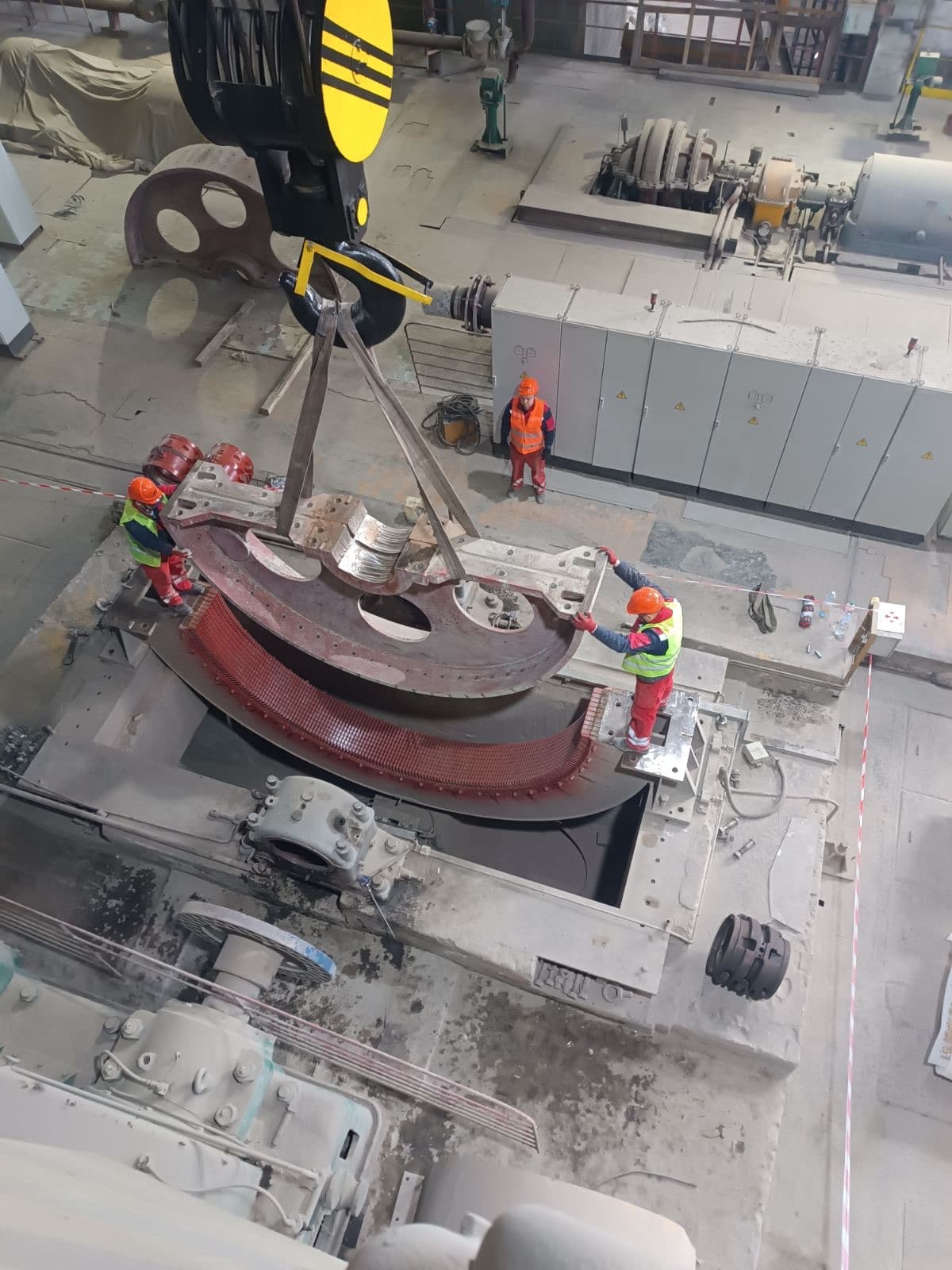
The following must be checked:

  • the shaft;
  • the bearings;
  • the bearing seats;
  • the end shields;
  • the frame;
  • the air gap;
  • the stator core;
  • the rotor core;
  • the winding;
  • the squirrel cage;
  • the balancing;
  • the axial position.

Simply cleaning up the rubbing marks is not enough. It is necessary to determine why the rotor was displaced.

Special aspects of repairing motors fed from a variable frequency drive

The following must be taken into account:

  • the pulsed voltage waveform;
  • steep voltage fronts;
  • overvoltage at the winding;
  • heating at low speed;
  • bearing currents;
  • high-frequency components;
  • the insulation requirements;
  • the cable length;
  • the filters;
  • the switching frequency settings;
  • the speed range.

During repair, the following may be recommended:

  • reinforced insulation;
  • phase-separated insulation;
  • an insulated bearing;
  • a grounding brush;
  • temperature sensors;
  • independent (forced) ventilation;
  • filters at the drive output.

Does a burnt-out motor always need to be rewound

Repair is not always worthwhile. The following must be considered:

  • the extent of the core damage;
  • the condition of the rotor;
  • the condition of the shaft;
  • the availability of materials;
  • the cost of a new motor;
  • the delivery time;
  • the energy efficiency;
  • the criticality of the equipment;
  • the ability to restore the factory parameters;
  • the availability of documentation.

For a standard low-power motor, replacement is sometimes more economical. For a large, special, high-voltage or imported motor, repair is often considerably faster and cheaper than manufacturing a new one.

How to assess the quality of a repair

Signs of a quality repair:

  • an incoming inspection was carried out;
  • the cause of the damage is recorded;
  • a defect report has been drawn up;
  • the winding data has been preserved or confirmed;
  • the core has been checked;
  • the rotor has been checked;
  • the fits have been measured;
  • run-out has been checked;
  • the rotor is balanced;
  • the bearings are correctly fitted;
  • electrical tests have been carried out;
  • a no-load test has been carried out;
  • the current and vibration have been measured;
  • test records have been prepared;
  • installation recommendations have been provided.

Fresh paint and a clean appearance alone do not confirm the quality of a repair.

Signs of a superficial or incomplete repair

The following should raise concern:

  • the absence of a defect report;
  • the absence of fit measurements;
  • bearing replacement without checking the shaft and the end shields;
  • rewinding without checking the core;
  • no balancing after rotor repair;
  • the absence of test records;
  • the absence of no-load test data;
  • no explanation of the cause of the failure;
  • the use of unidentified materials;
  • an inability to confirm the winding data;
  • painting over damaged surfaces without repairing them;
  • an unsuitable key or coupling;
  • unstable vibration after the repair.

What should not be done during repair

01

Do not start with rewinding before an inspection

A burnt winding may be only the consequence of another defect.
02

Do not discard the old winding before recording the data

Once it has been removed, some of the information cannot be recovered.

03

Do not burn out the winding at an uncontrolled temperature

This can damage the interlaminar insulation of the core.

04

Do not fit new bearings onto worn seats

The bearing will quickly lose its correct position.

05

Do not balance a bent shaft

Balancing weights do not eliminate a geometric defect.

06

Do not paint fitting or contact surfaces

Paint changes the dimensions and disrupts the contact.

07

Do not mix greases

Incompatibility can degrade the lubricating properties.

08

Do not overfill the bearing chamber

Excess grease causes heating.

09

Do not carry out a dangerous test start

A damaged rotor or fan can disintegrate.

10

Do not assess the insulation with a megohmmeter alone

It does not reveal all interturn defects.

11

Do not change the winding data without a calculation

This can completely change the characteristics of the motor.

12

Do not release the motor without verification tests

Even correctly performed individual jobs must be verified once the motor is assembled.

Typical mistakes during repair

  1. 01Incomplete recording of the initial condition.
  2. 02Lack of information about the failure regime.
  3. 03Incorrect disassembly.
  4. 04Damage to the end-turns while withdrawing the rotor.
  5. 05Uncontrolled heating of the coupling half.
  6. 06Damage to the shaft caused by a puller.
  7. 07Incorrect bearing removal.
  8. 08No measurement of the fits.
  9. 09Ignoring ovality and taper.
  10. 10Rewinding without checking the core.
  11. 11An error in the number of turns.
  12. 12An error in the connection diagram.
  13. 13Weak fastening of the end-turns.
  14. 14Poor soldering.
  15. 15Insufficient impregnation.
  16. 16An incorrect drying regime.
  17. 17Mixing incompatible greases.
  18. 18An incorrect internal bearing clearance.
  19. 19Transmitting the fitting force through the rolling elements.
  20. 20Incorrect axial adjustment.
  21. 21An uneven air gap.
  22. 22No balancing.
  23. 23No run-out check after the repair.
  24. 24No phase-by-phase check of the winding.
  25. 25No no-load test.
  26. 26Assessing the motor by noise level alone.
  27. 27No test records.
  28. 28An unestablished root cause of the damage.

Practical cases

01

After rewinding, the motor has an increased no-load current

Possible causes:

  • an incorrect number of turns;
  • a connection error;
  • an incorrect winding pitch;
  • core damage;
  • an uneven air gap;
  • rubbing;
  • a rotor defect;
  • excessive voltage.

It is not enough to limit the check to a repeat insulation resistance measurement.

02

New bearings heat up quickly

It is necessary to check:

  • the fits;
  • the internal clearance;
  • the amount of grease;
  • the compatibility of the grease;
  • the axial clamping;
  • misalignment of the end shields;
  • the alignment;
  • the vibration;
  • current flow through the bearings.
03

High vibration persists after the repair

Possible causes:

  • residual imbalance;
  • a bent shaft;
  • incorrect assembly;
  • misaligned end shields;
  • a soft foot;
  • a coupling defect;
  • electromagnetic asymmetry;
  • resonance of the test bench.
04

The winding has normal insulation resistance, but the motor hums and draws an uneven current

Possible causes:

  • an interturn short circuit;
  • an incorrect diagram;
  • an open circuit in a parallel branch;
  • a rotor defect;
  • an uneven air gap;
  • supply unbalance.

Additional electrical and mechanical checks are needed.

05

After the winding was replaced, the motor overheats under load

It is necessary to check:

  • the correctness of the winding data;
  • the actual load;
  • the cooling;
  • the voltage;
  • frequent starts;
  • the rotor;
  • the alignment;
  • the bearings;
  • the protection settings;
  • the variable frequency drive regime.
06

After the repair the motor runs normally on the test bench but vibrates on site

Likely external causes:

  • misalignment;
  • a soft foot;
  • the foundation;
  • the coupling;
  • pipe loads;
  • a defect in the driven machine;
  • structural resonance;
  • incorrect fastening.

Bench testing does not replace correct installation on site.

Step-by-step algorithm for a professional repair

STEP 01

Identify the motor

Record all the nameplate data and the completeness of the set.

STEP 02

Collect the failure history

Obtain data on the protection, the load, the vibration and the operating conditions.

STEP 03

Carry out an external inspection

Take photographs before cleaning.

STEP 04

Carry out the incoming measurements

Check the electrical and mechanical condition.

STEP 05

Mark the parts

Record the relative position of the assemblies.

STEP 06

Disassemble the motor

Without impacts or damage to the parts.

STEP 07

Clean and dry

While preserving the diagnostic indications.

STEP 08

Carry out a complete inspection

The stator, the rotor, the shaft, the end shields, the bearings, the frame and the auxiliary systems.

STEP 09

Establish the root cause

Separate the consequence from the source of the damage.

STEP 10

Draw up the defect report

Define the mandatory and recommended work.

STEP 11

Agree the scope of the repair

Record the technical decision.

STEP 12

Carry out the electrical repair

Rewinding, insulation, impregnation, repair of the connections.

STEP 13

Carry out the mechanical repair

The shaft, the seats, the end shields, the frame, the coupling, the fan.

STEP 14

Repair the rotor

The cage, the winding, the rings, the commutator or the poles.

STEP 15

Carry out an interim check

Before final assembly.

STEP 16

Balance the rotor

After completing all work that changes its mass.

STEP 17

Fit the bearings

Using the correct fitting method and lubricant.

STEP 18

Assemble the motor

With control of the clearances, the alignment and the axial position.

STEP 19

Carry out the electrical tests

Confirm the insulation, the connection diagram and the symmetry.

STEP 20

Carry out the no-load test

Monitor the current, the vibration, the noise and the temperature.

STEP 21

Prepare the test records

Retain all the actual results.

STEP 22

Prepare recommendations

On installation, protection, lubrication and further operation.

Control table of repair stages

StageMain checkResult
IntakeNameplate data, completenessAcceptance report
Incoming diagnosticsInsulation, resistance, play, run-outIncoming test record
DisassemblyMarking, photographs, preservation of tracesSet of parts
CleaningRemoval of contamination, dryingParts ready for inspection
InspectionStator, rotor, shaft, end shields, frameDefect report
Electrical repairWindings, insulation, impregnationRestored electrical part
Mechanical repairShaft, fits, frame, end shieldsRestored geometry
Rotor repairCage, rings, commutator, windingSound rotor
BalancingInitial and residual imbalanceBalancing record
AssemblyClearances, bearings, greaseAssembled motor
Electrical testingInsulation, resistance, diagramTest records
No-load testCurrent, vibration, noise, temperatureTest report
DispatchPainting, preservation, documentsFinished motor

Recommendations for the chief power engineer

Before handing the motor over for repair, it is advisable to provide:

  • the datasheet;
  • the diagram;
  • previous test records;
  • the repair history;
  • vibration data;
  • current data;
  • information on protection tripping;
  • the variable frequency drive settings;
  • bearing data;
  • the type of grease;
  • photos of the installation site;
  • information about the driven machine.

After the repair the following must be checked on site:

  • the foundation;
  • the soft foot;
  • the alignment;
  • the condition of the coupling;
  • the voltage;
  • phase unbalance;
  • the protection settings;
  • the lubrication;
  • the direction of rotation;
  • the vibration;
  • the temperature;
  • the actual load.

Even a well-repaired motor can fail again because of incorrect installation or an unsuitable operating regime.

Frequently asked questions

Where does an electric motor repair start?

With intake, collecting information about the fault, an external inspection and incoming diagnostics.

Does the motor always need to be fully disassembled?

No. It depends on the type of repair and the defect. But for a major overhaul or an emergency repair, complete disassembly is usually necessary.

Is it enough to replace the bearings?

Only if it has been confirmed that the shaft, the fits, the end shields, the lubrication, the alignment and the other assemblies are sound.

Does a burnt-out motor always need to be rewound?

If the winding has lost its electrical or mechanical strength — yes. But the core must first be checked and the cause of the overheating established.

Why check the core after removing the winding?

Shorted laminations increase local losses and can overheat the new winding.

Why is it necessary to record the old winding data?

To reproduce the motor's factory electromagnetic characteristics.

Can the power be increased during rewinding?

Not arbitrarily. The power is limited by the core, the cooling, the shaft, the bearings and other elements.

Does the rotor need to be balanced after rewinding the stator?

Rewinding the stator does not change the rotor's mass. But the rotor must be balanced if it was repaired, its parts were changed, or there is increased vibration.

Does the armature need to be balanced after rewinding?

Yes, because the mass distribution of the winding, the bandages and the impregnation changes.

Why measure shaft run-out?

To detect bending, eccentricity and misalignment of the fits, which are not corrected by balancing.

Can a new bearing be fitted onto a worn seat?

No. The seat must be restored or the part replaced.

Why must a bearing not be driven in with a hammer?

An impact can damage the raceways, the cage, the shaft and the seat.

Is impregnation of a new winding mandatory?

Yes. It provides dielectric strength, securing of the conductors and protection against moisture.

Is it enough to measure the insulation resistance after the repair?

No. Checking the phase resistance, the connection diagram, the interturn insulation and other tests are also needed.

Why carry out a no-load test?

To assess the current, the vibration, the noise, the temperature, the rotation and the operation of the bearing assemblies.

Can a motor be fully checked without load?

Not always. Some defects only appear under load.

Why can a motor vibrate after a quality repair?

Because of incorrect alignment, the foundation, the coupling, a soft foot, the driven machine or electromagnetic factors on site.

What should a quality repair report contain?

The defect report, the list of work carried out, the measurement results, the test records and recommendations.

How long does a repair take?

The duration depends on the power, the design, the extent of the damage, and whether parts and materials need to be manufactured.

When is repair not worthwhile?

When the main assemblies cannot be safely restored, or when the cost and risks significantly outweigh the benefits of replacement.

Turnkey electric motor repair and diagnostics

ELEKTROPROMREMONT LLC carries out comprehensive repair of industrial electric machines of various power ratings and designs.

The scope of work includes:

  • incoming diagnostics;
  • disassembly of electric motors;
  • cleaning and drying;
  • complete inspection;
  • stator rewinding;
  • coil manufacturing;
  • wound-rotor rewinding;
  • armature rewinding;
  • field winding repair;
  • squirrel-cage rotor repair;
  • replacement of bars and end rings;
  • commutator repair;
  • slip-ring repair;
  • brush-holder repair;
  • shaft repair;
  • shaft straightening;
  • restoration of bearing seats;
  • manufacturing new shafts;
  • end shield repair;
  • frame repair;
  • fan repair;
  • coupling-half repair;
  • bearing replacement;
  • dynamic balancing;
  • run-out monitoring;
  • air-gap monitoring;
  • vacuum impregnation;
  • winding drying;
  • electrical testing;
  • high-voltage withstand testing;
  • interturn insulation monitoring;
  • vibration testing;
  • no-load testing;
  • laser alignment;
  • non-destructive testing;
  • preparation of test records;
  • preparation of technical reports.

Conclusion

An electric motor repair is a consistent engineering process, not a set of isolated fitting or winding operations.

A quality repair must include:

  • correct intake;
  • collecting information about the failure;
  • incoming diagnostics;
  • photographic records;
  • controlled disassembly;
  • cleaning;
  • a complete inspection;
  • a search for the root cause;
  • restoration of the electrical part;
  • restoration of the mechanical part;
  • rotor repair;
  • balancing;
  • correct assembly;
  • electrical testing;
  • a no-load test;
  • monitoring of vibration and temperature;
  • preparation of the documentation.

It is not enough to replace the damaged part. It is necessary to establish why it was damaged, and to eliminate the factor that caused the failure.

This approach is what makes it possible not merely to start the motor after repair, but to restore its reliability and predictable service life.

Important disclaimer

This material is for informational purposes. The values, diagnostic methods, scope of work and recommendations given here are general and do not replace the manufacturer’s technical documentation. The final decision for a specific machine is made from its own diagnostics and inspection, taking into account its type, power, design, duty, operating history and applicable standards.

Need a motor repair?

We will carry out a complete incoming inspection, determine the root cause of the damage and perform the full restoration cycle — from rewinding the windings to verification testing on no load.

Get a consultation